
Power converter
A current transformer is a measuring transformer that converts a primary current into an electrical signal that is easy to process . Conventionally, this is understood to mean a transformer designed for measurement requirements , which is used for potential-free measurement of large alternating currents . Newer current transformer types do not require a transformer and can also measure primary direct current .
A classic current transformer emits a secondary current of milliamps to a few amps as an output signal , which is essentially proportional to the primary current. The current to be measured can be almost arbitrarily high with a correspondingly high number of turns ratio. In the case of a current transformer, the secondary current differs from the primary current by a phase shift angle that is approximately zero with a suitable connection.
In addition to core saturation, the magnetizing current associated with the conversion is one of the causes of measurement errors .

There are versions of current transformers for all voltage levels for use in the power grid . Current transformers have different characteristics depending on the application:
- For measuring purposes, to generate a current that is reduced proportionally as possible within the measuring range for current measuring devices , energy meters . Such transformers protect themselves and the connected measuring devices from overcurrent by going into saturation.
- for protection purposes, for the transmission of a reduced current to protection relays , control and regulating devices. Such converters deliver a primary current dependent output signal even with high overcurrents.
Structure and application
Inductive current transformers
Inductive current transformers have only one or a few primary turns through which the current to be measured flows, as well as a larger number of secondary turns. The primary winding often consists of a busbar guided through the toroidal core of the converter, which corresponds to a single primary winding. The secondary current is reduced compared to the primary current to be measured - inversely proportional to the ratio of the primary and secondary number of turns.
The secondary winding must z. B. connected to an ammeter or short-circuited, as otherwise high core losses or even dangerous voltages can occur on the secondary side. The maximum permissible secondary-side impedance must not be exceeded for proper operation. Current measuring devices (including current paths from power meters or energy meters ) or current-sensitive protective relays (bimetallic release or magnetic release) that can detect and evaluate overcurrent conditions can be located in the secondary circuit .

|

|
|
|
Principle of the straight-through transformer
|
Basic structure of a current transformer
|
The primary connections are often marked with P1 and P2 (formerly capital letters K and L), the secondary connections with S1 and S2 (formerly lowercase letters k and l). The label also indicates the polarity: P1 and S1 have the same polarity at the same time, that is, the current flows into P1 and the reduced current flows out of S1. In each case, it is the beginning of the winding.
Current transformers can be built for frequencies from 16 Hz up to the MHz range. The lower limit frequency is determined by the secondary inductance and the sum of its winding resistance and external burden (load). The time constant of the current, which decreases exponentially on the secondary side in the case of a square-wave signal on the primary side, is


With
| - secondary inductance | |
| - ohmic resistance of the secondary winding | |
| - burden |


Application in the power grid
Core material with the highest possible permeability is used, particularly in the power grid (50 or 60 Hz) or at a lower frequency . These are sheets or toroidal tape cores made of silicon-iron alloys or toroidal tape cores made of nanocrystalline alloys. They are implemented up to a primary rated current of around 50 kA.
For safety reasons, the secondary winding of current transformers in medium and high voltage networks is earthed on one side.

Current transformer for mounting on busbar (500 A)

Two current transformers (left and right) for 1 kA in the medium-voltage network

Current transformer for laboratory use with several measuring ranges
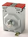
Current transformer for cabinet mounting
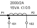
Connection identification with further characteristic data


Current transformers in the power grid are often designed as post insulators or bushings. Current transformers in the power grid must withstand high transient overcurrents and voltages. In addition to the measurement accuracy, they are therefore also determined by the thermal overcurrent resistance I th (e.g. 600 times the rated current or 60 kA) and the surge current resistance, largely determined by the mechanical resistance to magnetic forces (about 2.5 times the I th ), specified. The loads arise from short circuits and lightning strikes.
Applications in electronics
Current transformers of various designs are used in electronics and power electronics . They have to withstand less high overload requirements, but handle higher frequencies. Highly permeable ferrites are used at low frequencies, but also at proportionally higher frequencies, because or when the amplitude of the magnetic flux density is low. The designs range from hand-wound ferrite toroidal cores that are pushed onto component connection legs to solderable components with holes or with one or more current paths that can be connected in parallel or in series. One-time and periodic pulse currents as well as alternating currents of any curve shape can be measured, as long as it is ensured that the mean direct current is zero. This is the case when the positive and negative voltage-time integral are equal.
Other current transformers
Coreless current transducers see Rogowski coil .
In addition to inductive current transformers for measuring alternating current, there are also devices for measuring direct and mixed currents based on field plates or Hall sensors , see direct current converters .
In high voltage alternation as well as direct voltage applications , magneto-optical current converters based on the Faraday effect are also used for current measurement . An optical fiber is wound around the electrical conductor in the form of a coil; the current in the conductor leads to a rotation of the plane of polarization of the light beam in the optical fiber. This rotation can be measured optoelectronically. It is proportional to the current strength. In the electrochemical industry, direct current up to 500 kA is measured. This type of current transformer is also known as a fiber optic current sensor FOCS .
Identification for the company
Regular operation
Up to the primary rated current and within a specified load range, a current transformer behaves like an ideal current source or constant current source within the scope of its permissible measurement deviation ; their output current (secondary current) depends solely on the input current (primary current) and not on the load, up to the secondary rated current (preferably 5 A) according to the rated ratio . This is given as an unabridged fraction, e.g. B. 200 A / 5 A, often abbreviated to 200/5 A.


The translation measurement deviation (formerly the current measurement deviation ) is defined as a relative quantity by

with actual = primary current and = actual secondary current when flowing under measurement conditions.


The phase difference in the case of a sinusoidal curve between the secondary and the primary current vector is zero for the ideal current transformer. The actual difference is called the skew angle .
The highest permissible amount of the translation measurement deviation at the rated frequency and the highest permissible amount of the misalignment are defined by an accuracy class - different for current transformers for measuring purposes and current transformers for protection purposes.
The admittance of the secondary circuit that enables the secondary current is referred to as the burden . It is usually expressed in terms of the apparent power that is consumed with the secondary rated current and a specified load power factor (often 0.8 inductive). A special value of the burden, the design burden, is used as a basis for the accuracy specifications. Standard values of the rated power are 2.5… 30 VA.
| For class 0.2: Maximum amount ... |
at | |||
| 5% | 20% | 100% | 120% | |
| ... the translation measurement deviation |
0.75% | 0.35% | 0.2% | 0.2% |
| ... the wrong angle | 30 ' | 15 ' | 10 ' | 10 ' |

Limitation on the input side
Current transformers for measuring purposes are specified up to 120% of the rated current in the accuracy classes 0.1 - 0.2 - 0.5 - 1 (also 0.2S - 0.5S - 3 - 5; not dealt with here). The number stands for the highest permissible gear ratio measurement deviation in percent for the primary rated current and rated power. The first table shows the statements of the class symbol on various primary currents using the example of class 0.2.
| For class 5P20: Maximum amount ... |
at | |
| 1 | 20th | |
| ... the translation measurement deviation |
1 % | 5% |
| ... the wrong angle | 60 ' | - |
Current transformers for protection purposes are specified up to a rated accuracy limit current which is higher than the primary rated current by the accuracy limit factor. Standard values for this factor are 5… 30. For these converters, the letter P (for protection) and the accuracy limit factor are added to the number in the accuracy class; Standard values are classes 5P and 10P. The second table shows the statements using the example of class 5P20.
The current transformer can be described further by adding further letters to the P.
Limitation on the output side
The information on the measurement deviation applies to current transformers for measuring purposes for every load in the range of 25 ... 100% of the rated power, the information on current transformers for protective purposes only applies to the rated burden. The burden must have the specified power factor.
A secondary circuit that is not closed acts on the converter like a burden with an almost infinitely high resistance. The curve shape of the secondary signal is very strongly distorted because then the voltage-time area acting on the core and the coil is too large; see also the working principle of the transformer . The amount of voltage that occurs depends on the current strength, core cross-section and secondary number of turns. In the case of current transformers up to approx. 500/5 A and low rated outputs, the peak value of the "open" voltage usually remains below 200 V. However, larger transformers can cause higher voltage peaks, which pose a risk for people in the converter if the open terminals are touched can lead to breakdowns and flashovers between the terminals. The secondary circuits of current transformers must never be operated open , as life-threatening voltages can occur at the secondary terminals, especially with large currents and powerful cores. In other words: Current transformers when operated without connected measuring devices or other loads in the secondary circuit must be short-circuited at their terminals .
Summation current transformer


A special form of the current transformer is the summation current transformer, such as is used in residual current circuit breakers . All conductor currents ( outer and neutral conductors as forward and return conductors in a single-phase alternating current network - or all three outer conductors and the neutral conductor in three-phase alternating current ) are routed through a current transformer. Only the differential current from the conductors is then converted. For example, fault currents can be detected.
See also
Individual evidence
- ↑ a b c DIN EN 61869-1: 2010-04, also VDE 0414-9-1: Instrument transformers - Part 1: General requirements .
-
↑ a b c DIN EN 61869-2: 2013-07, also VDE 0414-9-2: Instrument transformers - Part 2: Additional requirements for current transformers.
For the previous standard DIN EN 60044-2, there was a transition period until October 2015. - ↑ http://www.vacuumschmelze.de/index.php?id=139
- ↑ From company documents [1] ; Retrieved April 26, 2017.
- ↑ According to VDE 0141, Section 5.3.4, current and voltage transformers should be earthed from a measurement voltage of ≥ 3.6 kV. In the case of low voltages (up to a measurement voltage of ≤ 1.2 kV), earthing can be omitted if the converter housing does not have large metal surfaces that can be touched.
- ↑ a b From factory documents [2] in the section on current transformers; Retrieved January 25, 2015.
- ↑ a b From company documents [3], pages 4, 5; accessed on November 2, 2016.
- ↑ From company documents [4] ; Retrieved April 26, 2017.
- ↑ P. Menke: Optical precision current sensor based on the Faraday effect . Dissertation, University of Kiel, 1996.
- ↑ Far superior to conventional instrument transformers. ABB Germany, May 15, 2006, accessed on July 23, 2019
- ↑ From company documents [5] (PDF) in chap. 1.4.7; Retrieved February 19, 2016.