
How the sewing machine works
This article describes the technical functioning of sewing and embroidery machines , i.e. the process developed between around 1830 and 1900 to create a desired seam using a machine. These procedures are an integral part of the machine's design and define how the thread or threads used are knotted in order to anchor it in the fabric. The pattern that is created with the seam is largely independent of the sewing process, although some special patterns are preferably created with a certain machine design.
The mechanical descriptions in this article are based on machines from the early 20th century. Their structure essentially corresponds to today's sewing or Schiffli embroidery machines , although some of the processes described are only rarely used. Where necessary, current versions are indicated or sections are marked as out of date. The fact that much is still valid has to do with the fact that the period between 1890 and 1910 is considered to be the heyday of the textile and especially the embroidery industry and therefore the most important discoveries also fell during this time.

Basics


In machine sewing, if the needle is to pierce the fabric and then come out of it, the needle thread must form a loop on the underside of the fabric. The thread stuck in the fabric is held back by the friction. In order to form a seam, a second thread must now be passed through the loop created, which prevents the loop from being pulled out of the fabric again, or the individual loops created one after the other must be linked to one another for the same purpose. In the first case one is dealing with two-thread sewing machines, which are divided into cord stitch and lockstitch machines, and in the latter case with single thread or chain stitch machines.
The sewing machine needle is designed so that it can produce the most reliable and flawless seam possible. The usual machine needle, straight or curved depending on its type of movement, has a long groove on one side (FIG. 1) which receives the thread coming from the thread reel , which prevents the formation of loops along this groove. On the other side of the needle facing the loop catcher, the thread connected to the fabric should throw a loop. This is made possible by the small cusp located in the long groove directly above the eye of the needle . The short needle groove opposite the long one only serves to protect the thread by taking it up while the fabric is piercing. The mechanical parts on the underside of the fabric and the machine that insert a second thread into the needle thread loop or enable one loop to be connected to the other are called loop catchers. They differ from one another in shape and working method, depending on the type of stitch to be formed. For general use three types of stitches are: the chain stitch , the cord-stitch and lock stitch .
Machines for different stitch types
Different types of stitches are used depending on the properties of the desired seam. As these differ fundamentally in some cases, the machines must be specially designed for certain seams. The main difference is whether you sew with one thread or with upper and lower threads. The chain stitch is done with one thread, the other methods described use two threads.
Chain stitch machines
The chain stitch or tambourine stitch is so called because of its chain-like appearance and, depending on the fabric thickness and stitch length, requires 3½-4 times the seam length of thread. It can be made by means of a rotating or oscillating gripper or by means of a crochet needle in connection with a looper. In the first two cases, the loop catcher below does not merely have to grasp the needle thread loop. He also has to hold on to it and stretch it until the needle has entered the open loop with the next stitch, after which he then grasps the new loop, which is now in the first and ties it. This process, on a Wilcox u. Gibbs gripper shown is illustrated by FIG.
Bonnaz's tambouring machine and several sewing machines used in the leather industry are based on the last-mentioned principle of making the chain stitch . While the needle is still in the last loop, the sewing thread is placed in the hook of the needle, which now pulls it through the last loop and thus locks it (Fig. 3). The hook of the hook needle is bent slightly inwards and its opening just needs to be filled with the thread to be used. A series of fully formed stitches is illustrated in FIG. 4. Once the looper has not grasped the loop; a skipped stitch has arisen from which the previous seam can be loosened. Even if you pull on the free end of the thread, the entire seam can be unthreaded again. To prevent this, it must be sewn on by hand afterwards. Chain stitch sewing machines are widely used for special purposes because of the elastic seam. Such a special machine is shown in FIG. 4b. One gives the Wilcox u. Gibbs gripper to achieve a particularly elastic seam, as is required for tricot sewing, a second point to the back, which causes the thread to be tightened more gently.

Fig. 2 u. 3. Chain stitch formation with two different methods
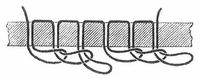
Fig. 4. Scheme of the chain stitch. A sewing error can be seen in the middle

Figure 4a. Chain stitch formation by hand. It can be clearly seen here why the stitch is so called.
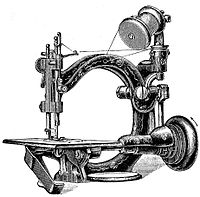
Figure 4b. Chain stitch sewing machine


Cord stitch machines
The cord stitch (knot, double chain stitch) requires 4½ to 6 times the seam length of thread, depending on the fabric thickness and stitch length. It can be produced by means of a pointed needle in connection with a vibrating, so-called circular needle, or with a second pointed needle with a double movement. A machine of the latter type is shown in Figure 5a. The formation of the stitch with the aid of the circular needle of Grover and Baker is shown in Fig. 5. The latter oscillates about the upper needle in an arc of about. As a result of the sliding up and down of the needle arm along a helically wound spindle, on the upper end of which it sits 240 °. The interlacing of the lower binding thread with the upper thread takes place in such a way (FIG. 6) that the binding thread goes through the first needle thread loop, then around the second loop, through the first back and into the second. So there is a penetration and wrapping of the upper thread loop.
This apparently complicated intertwining of the threads becomes immediately clear when one observes that while the circular needle is still in the first loop, the upper needle penetrates behind the thread of the circular needle, and this now winds out of the first upper thread loop and the upper needle and the next loop of the same wraps around. Once this is done, the upper needle forms a loop into which the circular needle penetrates as a result of a rotation opposite to the one just completed. So the game repeats itself.
In Fig. 6, which shows a number of fully formed stitches, two occurring types of skipped stitches are shown. With the skipped stitch a, the upper needle did not enter the loop of the circular needle; such a skipped stitch is not noticeable on the upper side of the fabric. On skipped stitch b, the circular needle did not enter the loop of the upper needle, and as a result, this loop is pulled up again and a long stitch is created. The cord seam is also detachable; because if you pull at the end of the thread c, all loops of the lower or binding thread wind out of those of the upper thread. The cord seam is now only used to create a very elastic seam or a decorative seam. In the latter case, cord stitch sewing machines with double stitch forming organs have even been used.

Fig. 5. Stitch formation with the circular needle
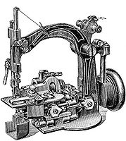
Figure 5a. Cord stitch machine
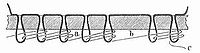
Fig. 6. Looping of the lower binding thread with the upper thread


The double lockstitch
The following procedures are common on newer sewing or embroidery machines. You use two threads. The needle thread is passed through the fabric from above. The bobbin thread is stored in a mostly movable capsule in the lower part of the machine.
The making of the stitch is done in such a way that either
- a second thread is fed into the loop of the upper thread by means of a shuttle ( long shuttle ) which holds the second thread on a bobbin inside;
- the upper thread is pulled around a stationary bobbin that receives the second thread by means of a gripper ;
- the upper thread by means of a claw-like shuttle ( Greiferschiffchen ) around a movable with this, the second thread summary coil is drawn.
Depending on which of these loop catcher mechanisms is used to produce the double or two-thread lockstitch, you are dealing with a long shuttle, rapier or rapier shuttle machine. The individual types of snare catchers break down into other special types:
| Longship | |||
| Straight long boat | Bow longship | ||
| Open on the side | Open at the back (cylinder boat) | Open on the side | Open at the back (cylinder boat) |
| Gripper | |||
| free running: ordinary gripper | closed running: ring gripper | ||
| Grab shuttle | |||
| free running: ordinary grab shuttle | closed running: ring shuttle | ||
Figures 7-14 show some of the characteristic loop catchers for two-line machines. Fig. 8 shows a laterally open straight long boat with an inserted bobbin. The thread receives the tension required for drawing the stitch partly through the storage of the bobbin between a piston and the rear wall of the boat, partly through the leaf spring located inside.
Shuttle embroidery machines use a similar process, which is why they are so named. The only difference is that dozens or hundreds of needles work in parallel.
The outer leaf spring is only used to guide the thread. It prevents the thread from colliding with the needle or the stuffing valve while the shuttle is moving back and forth. Fig. 8 illustrates an arched long boat open at the rear (cylinder boat). The bobbin lies loosely in the shuttle, and the thread is guided and tensioned at the same time by the external spring.
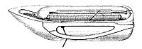
Fig. 7. Laterally open straight long boat
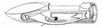
Fig. 8. Long, arched boat open at the back

Figure 8a. Underside of a bow-shaped longship sewing machine


In the case of the ring shuttle (Fig. 9), the thread tensioning spring is attached to the foldable cover of the same. The coil is caught and held by the edge protruding from the inside of the lid, against which the coil is pressed by means of a delicate leaf spring. 10 shows a rotating ring gripper with a driver. The former has a pin in the middle onto which the coil and the capsule surrounding it, which carries the tension spring, is pushed.
- Ring gripper

Fig. 9. Ring shuttle

Fig. 10. Ring gripper

Fig. 11. Oscillating ring gripper, only the front half is shown

Fig. 12. Spool housing

Fig. 13 and 14 Coupling of the bobbin case with the gripper. Front and side views

Figure 14a. Ring hook with bobbin case of a modern sewing machine

Figure 14b. Ring gripper capsule

Figure 14c. Stitch formation with the ring gripper

Figure 14d. Animation of the sewing process with a ring gripper


The whole thing is held against sliding off the pin of the gripper by an advanced lever. Fig. 11 shows one half of the ring gripper. The bobbin case is placed on the middle axle. The bobbin case is shown in FIG. The coil is inserted into the housing and this is then placed on the mandrel of the gripper. A notch or a protruding groove ensures that the bobbin case can only be inserted into the ring gripper in one position and is protected against twisting. The thread protrudes from the notch in the bobbin case and is protected from uncontrolled unwinding by a weak spring. A slightly different coupling of the bobbin case to the gripper is shown in FIGS. 13 and 14; it occurs on the Phoenix M machine. The bobbin case has a rib with which it engages in a groove located in the bowl of the gripper. The housing is pushed into the groove from the side and held in it by a locking piece.
Figure 14d. shows by means of an animation how sewing works with a ring gripper. Most modern sewing machines use a construction that corresponds in principle to this method with ring gripper and capsule.

In shuttle machines, the bobbin thread is tightened by extending the shuttle; For this purpose, looper machines have lugs or rising edges on the looper, along which the bobbin thread slides and is pulled out of the bobbin at the appropriate moment. In some gripper machines, too, the lower thread is pulled by means of a special slider that grips it and is equipped with a thread catcher. The manner in which the upper thread is interlocked with the lower thread can be seen from FIGS. 15 and 16. In FIG. 16, a skipped stitch is also shown. Failure to grasp the needle thread loop results in only one long stitch and has no effect on the strength of the seam. If the stitch width is not too large, such errors are hardly noticeable with a straight stitch. In embroidery, however, such errors are serious because the fabric moves in a different direction after each stitch and therefore a noticeable gap can appear if a stitch is omitted.

This feature of the lock stitch in connection with its low thread consumption makes it suitable for general use over the chain and string stitch . Long shuttle machines of all types sew forwards and backwards, because the loop catcher with the bobbin thread remains within the upper thread loop, always the simple lockstitch. On the other hand, machines in which the bobbin thread is located outside the needle thread loop from the start and only gets into the loop by pulling the upper thread over the bobbin using the loop catcher do not always sew the single lockstitch forwards or backwards, but sometimes the knotted double lockstitch, which is shown in FIG.
The loop formation (Fig. 18 and 19) of the older Wheeler & Wilson machine with a curved needle requires a special explanation , because with this one only the following loop pulls the previous one away and closed. The first loop is held up by a brush placed on the edge of the hook until the second loop is gripped by the hook tip, and then the first loop can slip through between the brush and the hook because a recessed part, the thread waste surface of the hook, is on the brush got on.
Special seams

Of the other seams to be mentioned, the overlay and the decorative seam should be emphasized. The former is particularly used for trimming buttonholes . Either the fabric is guided back and forth under the needle, or the needle is moved perpendicularly to it in addition to the movement in the direction of its axis. In both cases, the needle pierces alternately once into the opening and then into the edge of the buttonhole, creating a seam around the edge of the same. Such a machine is shown in FIG. 19a. The overlap seam can also be made with the help of a loop layer. Decorative seams of various types can easily be produced if the needle bar is given a variable transverse movement in addition to its usual movement and if a material pusher is used at the same time, which pushes the material forwards and backwards at different stitch lengths.
Special feet or special needles are added to the sewing machines for special sewing work, for example hemming, capping, sewing on tapes, edging tapes, gathering, folding, sewing on cords, sewing decorative stitches.
Material transport

In addition to the stitch-forming organs (needle and loop catchers), every sewing machine needs a mechanism that advances the fabric as soon as the needle leaves the fabric. This is the knife gate valve. As a rule, this consists of a straight rail that goes back and forth and up and down, on which a toothed, height-adjustable flap sits, which directly feeds the fabric. The movement of the rail, known as Wilson's quadrangular movement, is partly frictional and partly inevitable . With fast machines (3000 stitches per minute) it has to be absolutely necessary. The transport can also be done by a periodically rotating, finely toothed wheel (push wheel), or with the help of the toothed, on some machines with a presser foot that can be adjusted in each direction. There are also machines that have both a lower and an upper transport guide in order to ensure that the material is fed as evenly as possible.
The rash of the fabric slide, d. H. its setting to the desired stitch length is regulated by the stitch regulator; however, in the case of the square-shaped push rods in different ways. The largest deflection (largest stitch) of the material slide is determined by the start and end point of its movement. Now you can shorten the path of the material slide either by starting its movement from the starting point of the largest stitch and stopping before the end point, or by allowing the movement to stop at the end point but start after the starting point. Both types of stitch modification are in use; the latter is the simpler one but is still only rarely used (for example with the machine in Table I, Fig. 3 below). The knife-edge valve is moved by a non-circular disc and, in the event of a smaller stitch, is moved away from the same by means of the stitch regulator, so that its eccentricity is not fully utilized. The second type of stitch change can be done in four ways, the best and most widely used being the one discussed here. A lever which is coupled to the fabric pusher rail and which has a variable pivot point lies against the material pusher eccentric, which regulates the feed. The displacement of the latter by means of the stitch regulator allows the eccentricity of the feed eccentric to be used to change the stitch within given limits. Knife pusher construction of the latter type shows the bottom view of the machine 2 on panel I. By means of the material presser under spring pressure (panel I. Fig. 8, and panel II, Fig. 4), the fabric is pressed down on the material pusher; a lever lifts it up to either follow the seam or remove the fabric.
The loose thread required during the stitch formation period for the needle and the loop catcher and its removal after the stitch formation is carried out by the thread take-up device by alternately shortening and lengthening the path of the thread between the tensioner and the eye of the needle. By shortening the path, loose thread is obtained. The activation of a thread feeder in the path of the thread prescribed by eyelets etc., d. H. into the thread line, makes this movable, since the thread take-up device itself has to be movable. The thread take-up device usually consists of a swinging lever which receives its movement from the needle bar or a cam mechanism (panel I, Fig. 6, and panel II, Fig. 4). If the thread is fed without a lever, i.e. directly through the needle bar, then clamping tension is required in front of the eye of the needle, which holds the thread in place until the point of the needle sticks into the fabric and then releases it. Alternatively, a thread take-up spring can be used which pulls the thread that has been loosened too early by the needle bar away and which hits a stop as soon as the needle sticks into the fabric in order to leave the loosened thread available. Thread feeders rotating at a uniform or non-uniform speed have been designed for fast sewing hook machines. Here, the thread path is alternately shortened and lengthened by the fact that the movable thread support located within two disks enclosing the thread and rotating with them changes its location for two fixed thread supports. The movement of the thread feeder is uniformly rotating when the loop catcher also revolves uniformly, but rotates two or three times during the one-off rise and fall of the needle; the latter only for the purpose of avoiding jolts in the machine which result from the irregular movement. A machine of this type is shown in Table I, Fig. 10, and Table II, Fig. 1.

If the loop catcher rotates at a non-uniform speed, so does the rotating thread feeder, using the mechanical means that are also used for the loop catcher. A thread dispenser of the latter type, used in the Phoenix M machine (panel II, FIG. 2), is shown in FIGS. 21. Is the thread line as with the older Wheeler u. Wilson machine (panel I, Fig. 8), the loose thread required during the stitch formation period is pulled off the thread reel by the loop catcher right at the beginning (Fig. 18 and 19) and, as has already been mentioned, the previous stitch only finished by the next one.
Tension formation
Since the tension of the thread has the greatest influence on the success of the seam, every sewing machine also requires tensioning devices for the upper and lower thread. When discussing the loop catcher, the lower thread tension was already mentioned. The upper thread gets its tension either by clamping it between discs, or by wrapping it once around the groove of a rotating disc under spring pressure, or finally by winding it several times around the surface of a rotating body. In all cases the friction that the pulled thread has to overcome is the cause of the tension. In the first two cases, by means of tension releases, usually by lifting the fabric press lever, the tensioning device is put out of action when the fabric is to be removed from the machine.
Rewinding devices

Separate bobbins are required for winding the bobbin thread onto the special bobbins. They are of simple construction for the gripper and shuttle shuttle machines. For this they have a shaft driven by the flywheel , onto which the bobbin is attached, and the line of the thread onto the bobbin is mostly done by hand, which is completely sufficient because of the small width of the same. The automatic winding of the thread has been introduced for the longer shuttle bobbins, but also for wider looper bobbins. The carter coils have particularly proven themselves. Their construction is based on the fact that the thread, after it has passed through a gentle clamping tension, passes over a parabolic guide bar and from there to the rotating bobbin. By virtue of the guide bar, thread by thread is laid down, and this regular winding is guaranteed by a springy flap that lies against the bobbin, which is gradually pushed back by the filling bobbin and, when the bobbin is full, triggers a pawl that previously connected the bobbin winder to the Has kept the flywheel pressed. The winding stops automatically after the trigger.
Switching between rewinding and sewing is usually done by means of a corresponding clutch in the flywheel. The inner axis of the flywheel, which is clearly visible in the right-hand machines in FIG. 22, is used for this purpose and can be disengaged by holding the flywheel and rotating the axis.
In industrial sewing machines, a belt pulley is coupled into the transmission between the electric motor and the drive wheel of the sewing machine, which drives the bobbin by means of a mechanism in order to rewind the thread.
Darning and embroidery
The sewing machine can also be used for darning and embroidery work and sometimes even for crocheting. Darning and embroidery is done using a frame in which the fabric is clamped. This is now pushed back and forth by hand under the needle in the required stitch length, after having previously made the material presser and material slide ineffective and given a loose tension.
Application forms
There are sewing machines for all industrial and home needs. For manual operation of the sewing machine, gear reduction gear with a gear ratio of 2½ was common. A characteristic example of this was the "Meissen" hand machine (panel I, fig. 1 and 2). When operated by foot, the machine rests on a wooden plate that is screwed onto an iron frame. A step in connection with a push rod and crank axle sets a cord pulley on the latter in rotation, which by means of a belt transmits its movement to the cord pulley of the machine. The gear ratio is 1: 4 to 1: 7. Several manufacturers have used ball bearings for the step bar and the flywheel of the frame to achieve easy movement. Sewing machines with mechanical foot drive are sometimes still available in third world countries if no electricity is available. However, the electrical machines also have a foot switch with which the speed of the machine can be regulated while both hands remain free to guide the fabric.
The following section should be read from the point of view of the 1905 encyclopedia writer. Since today - except in third world countries , as indicated above - electricity is widely available and electric motors can be built in any size, modern sewing machines are always operated with a built-in electric motor. Of course, nobody uses transmission drives or even steam engines for this anymore.
While the hand sewer makes a maximum of 50 stitches per minute, the machine sewer can make 500-600 and sometimes even 1000 stitches. The operation of individual machines by motors is hardly considered, although attempts in this direction have been made with spring, water, steam and electric motors. The spring motors are unsuitable for operation because the energy absorption capacity of the steel spring is too low. The water motors are too expensive and the steam motors are a nuisance to operate. The electrical operation by small dynamo machines, which seem to be coming more and more recently, requires an electricity system to which the dynamo coupled to the sewing machine can be connected. The propulsion by galvanic batteries or accumulators is excluded because of the multiple inconveniences of the former and the severity of the latter. When operating several sewing machines by elementary force, the type of motor is not important, only the direct drive of the sewing machines is of interest. These are set up on a workbench and are driven individually by belt operation from one friction transmission. All countershafts are driven by a transmission shaft, and their connection can be released or established with each machine by a step or lever, so that the machine can be quickly put into operation and out of operation. The speed that can be given to the sewing machine in individual cases finds its natural limit in the heating of the needle, which occurs sooner or later depending on the softness and porosity of the fabric. In order to extend the heating limit, the needle upwards of the eye has been made thinner for certain manufacturing purposes, so that the friction of the same in the fabric is reduced. The maximum speed limit is 3–4000 stitches per minute with very soft, porous fabrics. According to Loos, a sewing machine needs an average of 1/20 with around 700 stitches per minute including transmission. Horse power, 1/3 of which is accounted for by the machine itself, so that this requires 1/60 horse power to operate. Of course, this can only be used as an approximation, since the type of machine and especially the type of work is important. 1 horse power should be sufficient for 16 machines.
Identification of some sewing machine systems


The sewing machines described here date from 1900. Due to their sometimes quite coarse mechanics, how they work is easier to see than on a modern machine.
Table I, Fig. 1 and 2. Hand machine "Meißen" by Biesolt u. Locke in Meissen. Straight-long shuttle system with manual operation that can be engaged and disengaged from the side. If this is disengaged, the machine can also be used as a foot machine. The thread dispenser is moved by a needle bar that is actuated by a heart curve in conjunction with a crank disk and friction roller. The lower mechanisms are driven by a vertical shaft that is connected to the drive shaft by conical wheels. The knife gate valve is a combination between a force-fit and a positive design. The shuttle slide, connected to the shuttle basket, runs in a straight line across the knife and is driven by means of a common crank mechanism.
Table I, Fig. 3. Machine "Dürkopp A" by Dürkopp u. Comp. In Bielefeld. Arch-long shuttle system for foot operation. Thread feeder moved by cam roller. The shuttle is moved by a two-armed lever in conjunction with an angle lever, which is coupled to the eccentric rod that rotates the knife shaft. The stitch is shortened by moving the material slide away from the feed eccentric. Non-positive knife gate valve that gets its square movement from just one eccentric. Suitable for household and commercial use.
Panel I, Figs. 4 and 4 5. Pfaff ring shuttle machine from GM Pfaff in Kaiserslautern. Grab shuttle system for foot operation. Thread feeder moved by cam roller. Grab shuttle oscillates in a closed ring; it is driven by a multiple crank mechanism. Inevitable material feed. The horizontal movement of the feeder is derived from the drive shaft, the vertical movement from the lower auxiliary shaft. Suitable for commercial work.
Panel I, Figs. 6 and 7 7. "Veritas" machine from Clemens Müller in Dresden. Arch-long shuttle system for foot operation. Thread feeder moved by cam roller. The lower mechanisms are driven by an oscillating vertical shaft which encompasses the inclined drive shaft by means of an adjustable fork. Inevitable knife gate valve that is operated by a curved eccentric located on the horizontal shaft for back and forth movement and by a cam attached to the shuttle driver for ascending and descending. Suitable for household and commercial use.
Table I, Fig. 8. Gripper machine with curved needle from the stock corporation formerly Frister u. Rossmann in Berlin. Gripper machine for foot operation. Immovable thread line, therefore working without a thread dispenser. Non-positive, forked knife gate valve. Sewing arm running in cylindrical, adjustable bearings. Especially for sewing white goods.
Plate I, Fig. 9. Machine "Viktoria" by H. Mundlos a. Comp. In Magdeburg. Arch long shuttle system for foot operation with cylinder shuttle. Thread feeder moved by cam roller. Positive knife-feeder operated by two shafts. The feed shaft is moved from the upper shaft. Stitch position in the arm brought on. Shaft for the vertical movement of the material pusher operated by a curve on the shuttle driver lever. Suitable for household and commercial use.
Table I, Fig. 10, and Table II, Fig. 1. Dürkopp's high-speed sewing machine from Dürkopp u. Comp. In Bielefeld. W & G looper system in which the looper rotates to the left and the tip is behind the needle. The upper thread loop is rotated 180 ° when passing over the lower thread bobbin, but is then turned back again. The knotted double lockstitch is formed by sewing backwards. The hook makes three revolutions during the single up and down movement of the needle. The gripper shaft is driven by pin wheels and perforated belts. Uniformly rotating thread feeder. Stitch position by moving a circular eccentric perpendicular to the main shaft. Pivot joints are replaced by leaf spring joints (Fig. 12). Machine making up to 2500 stitches per minute, suitable for power operation.
Table II, Fig. 2. Phönix-M machine from Baer u. Push in Bielefeld. Looper system in which the looper rotates to the right and its point is in front of the needle. The upper thread is rotated 180 ° when passing over the lower thread bobbin, but is then turned back again. Sewing forwards and backwards creates the simple lockstitch. The gripper shaft is driven by the cranked main shaft through a slotted push rod and link crank, the spool housing is provided with a rib and running in the groove of the gripper bowl. Unevenly rotating thread feeder. Up to 2500 stitches per minute, is suitable for power operation.
Table II, Fig. 3. Line stitch machine from E. Böttcher in Berlin with two eye-pointed needles. Machine has hemmer and fabric cutter. It is built as a cylinder machine and is therefore used to sew woolen tubular fabrics that require a particularly elastic seam. Inevitable knife gate valve. Threading through the needle bar.
Table II, Fig. 4. Phoenix ring gripper machine from Baer u. Push in Bielefeld. Ring gripper machine according to Wheeler u. Wilson system. Gripper is eccentric to the driver and rotates unevenly due to the connection of the rear lower shaft with the front gripper shaft by a so-called. Crank coupling. Knife slide pushes forwards and backwards. Fabric press fan. Foldable spool pin. Suitable for cloth and leather work.
Table II, Fig. 5. Lockstitch buttonhole sewing machine "Perfecta" by James Gutmann in Berlin. The buttonhole is trimmed by a laterally swinging needle and fed by means of a fabric clamp, which is moved by mechanisms located below the sewing plate. Locking at both ends of the buttonhole. If the same is trimmed on both sides and both ends are locked, an automatic cutting device separates the hem edges from one another. Machine disengages automatically at the highest needle position. It is designed for lingerie manufacturing. Output: 1500–2000 buttonholes in 10 hours.
Table II, Fig. 6. Interlock overlock sewing machine from Union Sewing Machine Factory , GmbH in Stuttgart. The machine is used for trimming the edges of tricot goods or for sewing together butt-butted goods using overlock stitches. The needle thread is pulled over the edge of the fabric by a gripper swinging transversely to the seam and linked with a thread laid in a zigzag through a rug. For the latter, as for the needle thread, a special threading is provided. The knife gate valve is inevitable. In order to make the seam quite elastic, there is a row of fabric upset teeth in front of the fabric slide teeth, which have their own movement compared to the first and thus compress the fabric. Machine designed for power operation, makes 3000 stitches per minute.
Plate II, Fig. 7. Chain stitch machine from E. Böttcher in Berlin with a two-pointed Wilcox u. Gibbs gripper, automatic tensioning with controllable thread output. Take-up lever u. Fabric cutter. Suitable for the manufacture of woolen goods and jerseys.
working conditions
The following section, in the original quote from 1905, describes the sometimes poor ergonomics of hand and foot sewing machines. There is something similar to report about the hand embroidery machine , for example in the St. Gallen embroidery article . The only noticeable difference is that the embroidery machine was used almost exclusively by men, while the sewing machine was also used exclusively by women.
The commercial sewing machine work, in which the machine is moved by the foot, often causes all kinds of nervous disorders in healthy girls and women ( palpitations , ringing in the ears , lower back and loin pain ), but the abdominal organs are particularly affected. Women with abdominal disease are almost always harmed. With great exertion, employment neuroses occur, muscle pain, disturbances in the nutrition of the muscles, etc. Overworking of the heart can lead to permanent infirmity . With prolonged sewing machine work, digestive disorders often occur, which affect overall nutrition. Abdominal diseases are also generated, and sewing machine work is very harmful to pregnant women. It is not uncommon for adolescents to suffer from the long stooped posture, which leads to curvatures, high shoulders, etc. All damage occurs to a greater extent with very long working hours, when girls are employed too young, in poor work rooms, when working with tuberculous people and when poor nutrition is required due to low earnings. The damage caused by sewing machine work as such can be almost completely avoided if the machine is driven by a motor.
history
The following paragraph documents the development of machine sewing processes in the 19th century. For the general history of sewing machines, see the main article.
The first attempts to sew by mechanical means date from the end of the 18th century. In 1790, Th. Saint took an English patent on a machine for sewing soles that worked with an endless thread and probably produced the chain stitch. J. Madersperger in Vienna first (1807-39) used two threads to form a seam and based on the method of weaving. He also used the pointed needle. His machine, designed for sewing quilts, was unsuccessful because of its structural imperfections. In 1830, Thimonnier built a usable chain stitch producing machine, which was said to have been made in 80 copies and used especially for the production of military clothing.
Howe solved the problem of machine sewing with real success in 1845, because he grasped the right idea for its solution and also knew how to execute it constructively in a sufficient manner. Hunt in New York had built a machine according to Howes principles in 1834, but was unsuccessful. Howe used a needle with the eye close to the point and a shuttle as a stitch-forming device on his machine. The discontinuous material feed was imperfect on his machine. It was done by means of a stapling plate, moved by a drive and a rack, on which the fabric was placed. This mode of transport, which was limited to the length of the rack and which, moreover, only allowed the sewing of straight seams, had to be an obstacle to the general introduction of the sewing machine. In 1851 Singer improved the feed of the fabric by using a finely toothed indexing wheel located underneath the fabric in conjunction with a presser foot that was under spring pressure and pressed on the fabric. However, since the material is constantly under pressure on the transport wheel, its maneuverability is insufficient. Recognizing this, in 1852 Wilson invented the continuously operating knife-gate valve with a square movement, which, because it sinks under the sewing plate after each stitch is completed, does not prevent the material from being steered.
Wickersham invented overhead transport in 1853 by using the toothed presser foot as a material pusher. With these inventions, sewing machine construction had come to a preliminary conclusion. The further training of the snare catchers had not been neglected in the attempt to circumvent the Howeschen patents. Wilson had invented the hook for making the lockstitch as early as 1851 and Grover had invented the circular needle for making the cord stitch in 1852. Gibbs followed suit with the invention of the chain stitch looper in 1857. These valuable inventions quickly made the sewing machine useful for commercial and family purposes and explain the rapid development of the sewing machine industry in the United States of America. By 1859, 104,000 machines had been designed and sold here. Since the chain stitch sewing machines have the disadvantage of the easily detachable seam, the cord stitch machines consume too much thread and the Wheeler u. Wilson machines with curved needles easily fail in their functions, all of these machines were gradually replaced from family use by the A machine (panel I, Figs. 1 and 2) brought onto the market by Singer in 1859. With the introduction of this system, the German sewing machine industry in particular flourished. She has only advocated its improvement.
The Wheeler u. Wilson Co. exhibited their straight-needle Wheeler u designed by House at the 1873 Vienna World Exhibition . Wilson No. 8 machine, which has the advantage over the older machine that stitch by stitch is formed straight away. This is achieved by the non-uniform movement of the hook shaft with the simultaneous use of a thread feeder moved by a cam gear (panel II, Fig. 4). Because the Singer-A-construction is accused of having a difficult gait, especially caused by the shuttle slide that is being guided in a slideway, so in addition to the Wheeler u. Wilson No. 8 a series of shuttle machines (White, Domestic, New Home and other and later the Vibrating Shuttle of the Singer Company), which, in the style of the older Grover et al. Baker shuttle machine, have a shuttle swinging freely in a curve (panel I, Fig. 3 and 6, 7, 9). In addition, the passage space on these machines was enlarged; high-armed machines were created.
Because of their slow pace, the shuttle machines are not always sufficient for the industry. After Leslie's predecessor, the Singer Co. appeared at the end of the 1870s with a new type of snare catcher. She brought the von Diehl u. Miller designed a ring shuttle machine with an oscillating gripper shuttle especially intended for commercial purposes (panel I, Figs. 4 and 5). The Wheeler u. Wilson followed this procedure with the construction of the ring gripper machine (panel II, Fig. 4), in which the ring gripper is mounted eccentrically to the driver, which enables the needle thread to slip through unhindered between the hook and driver. The Standard Co. in the United States of North America had at the same time brought another ring gripper machine, built by the Mack Brothers, on the market, in which the gripper is driven alternately by two pins which receive their movement from a cam gear. The Wheeler u. Wilson Co. later acquired Wheeler u. Wilson no. 8 redesigned and the thread dispenser conveniently placed in the front of the arm like the Singer ring shuttle machine. Later this company brought out a machine W. G, W. Nr. 11, the gripper of which, according to Wardwell's process, has a groove inside in which the bobbin case is mounted, this arrangement avoids the use of the otherwise usual glasses to hold the bobbin case. Later, in order to be able to use large coils, the Singer Co. constructed a machine with an oscillating ring gripper while retaining the drive mechanism of their ring shuttle machine. The oscillating movement makes special devices superfluous, which aim to allow the upper thread to slip past unhindered between the driver and the loop catcher. The desire to increase the sewing speed moved Wilcox et al. Gibbs Co. for the construction of a rotary thread feeder (Panel I, Fig. 10, and Panel II, Fig. 1).
swell
- Sewing machine . In: Meyers Großes Konversations-Lexikon . 6th edition. Volume 14, Bibliographisches Institut, Leipzig / Vienna 1908, pp. 383–390 .
- Lexicon of technology ; Ex libris; Zurich 1972