
Turned part (workpiece)


As a rotary member in the are Zerspantechnik the workpieces designated by the manufacturing process turning to be processed. Analogously, one speaks of a casting or a forged part if it is to be or has been machined by casting or forging .
Turned parts predominantly have a rotationally symmetrical shape. Typical turned parts are screws, axles, shafts, spindles and wheel hubs. There can also be threads or centric bores that can be easily produced on lathes . Eccentric bores or bores that are at a certain angle to the axis of rotation can also be produced on lathes if driven tools are available there.
species
Depending on the ratio of length to diameter and the raw parts, a distinction is made between chuck parts , wave-shaped turned parts , discs and rod parts , as well as tip parts :
- Chuck parts are turned parts, the diameter of which corresponds roughly to the length. They are clamped on one side in lathe chucks .
- Shaft parts are shaped like a wave . Their length is a multiple of the diameter. Due to their own weight, the processing forces and imbalances, they bend more than chuck parts and therefore have to be additionally supported. Medium- length turned parts are supported at the second end with the tailstock , longer parts are also supported halfway along with a steady rest .
- Disc-shaped parts have a large diameter compared to the other dimensions. They are preferably machined on facing lathes . If they are hollow on the inside and practically only consist of a thin, narrow ring, they can become severely deformed during processing. For these cases, there are special clamping systems in which a particularly large number of or fully encompassing clamping jaws clamp around the circumference at the same time.
- In the case of rod parts, a rod is used as the raw part, the diameter of which roughly corresponds to that of the workpiece and the length of which is a multiple of the workpiece. These bars are often fed to the lathe using a bar loader . The main spindle is often hollow so that the raw part is fed through it and can be fixed using a collet . After machining, the work piece is separated from the bar by means of parting and turning and the bar is pushed further into the machine so that another workpiece can be machined. "Turning off the peg" is particularly common in automatic lathes and in series production.
- Tip parts are turned parts that are clamped and turned between centers .
- Turned parts in the diameter range from 0.1 to 32 mm are called precision turned parts. These are mainly used in sensor, magnet, measurement and medical technology . There are fasteners such. B. Titanium screws and threaded sleeves made of gold-platinum alloys are used in modern medical technology.
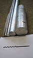
various materials as bar material with different diameters and lengths for the production of turned parts
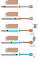
Machining of rod parts
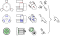
Lining parts
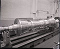
A particularly large part of the shaft (part of a turbine)


_-_BEIC_6365904.jpg)
Design of turned parts
With the design of the turned parts, the designer has a major influence on the costs incurred for production. There are therefore a number of design guidelines. Basically, the workpieces should be designed so that processing is as simple as possible.
- Surfaces with a high surface quality (low roughness) are more complex to manufacture than surfaces with great roughness. If, for technical reasons, a slight roughness is required, for example with bearing seats , these should be limited in length and offset from adjacent surfaces.
- Turned parts with large differences in diameter require a lot of effort because a lot of material has to be separated from the raw part. Processing therefore takes a long time and the material is used inefficiently. It is often cheaper to manufacture two separate parts and then join them together.
- Production becomes cheaper if the tools can move beyond the surfaces to be produced (so-called tool run-out).
- Transitions between different diameters are often rounded on turned parts in order to reduce the notch effect and thus improve strength . If all roundings have the same (large) radius, they can be machined with a round turning tool whose radius corresponds to that of the workpiece ( profile turning ). With different radii, either different tools are required or universal tools that generate the radii through their movement, which takes longer. With powerful CNC controls and modern tools, shaping / profile tools are becoming increasingly less important.
- When machining with profile tools, the existing differences in diameter should be as small as possible. Since the speed is constant, there is a different cutting speed over the radius . Since this has a major influence on tool wear, this is avoided as far as possible.
literature
- Herbert Schönherr: Machining , Oldenbourg, 2002, p. 110, 137.
- Andreas Hirsch: Machine tools - basics, design, exemplary embodiments , 2nd edition, 2012, Springer, pp. 240-254.
Individual evidence
- ^ Bahmann: Machine tools compact , 21st edition, Springer, pp. 130f., 134-137.
- ↑ Hirsch: Werkzeugmaschinen , Springer, 2nd edition, 2012, pp. 3, 240, 243, 245, 252f.
- ↑ Neugebauer (Ed.): Werkzeugmaschinen , Springer, pp. 101, 88, 92.
- ↑ Alfred Herbert Fritz, Günter Schulze (Ed.): Fertigungstechnik , Springer, 2015, 11th edition, pp. 419–421.
- ↑ Herbert Schönherr: Machining , Oldenbourg, 2002, p. 139 f.
- ↑ Herbert Schönherr: Machining , Oldenbourg, 2002, p. 140.
- ↑ Herbert Schönherr: Machining , Oldenbourg, 2002, p. 140.
- ↑ Herbert Schönherr: Machining , Oldenbourg, 2002, p. 141.