Dipole antenna
A dipole antenna (from Latin di 'two'; German two-pole antenna ; also antenna dipole ) is an elongated antenna that consists of two (possibly folded) straight metal rods or wires, which are also made in one piece in the case of the omega feed . It converts high-frequency alternating current and electromagnetic waves into one another and can therefore be used for both sending and receiving . So here the reciprocity law applies .
The optimal length of a λ / 2 dipole antenna, neglecting the shortening factor, is half the wavelength λ of the feeding high-frequency alternating current. Shortening or lengthening the antenna results in a corresponding change in the resonance frequency . Shortening means increasing frequency and vice versa.
history
The principle of the dipole antenna goes back to the German physicist Heinrich Hertz , who was the first to be able to demonstrate experimentally electromagnetic waves. Its dipole ( Hertzian dipole ), which was much smaller than λ / 8, has only theoretical significance. The extension to about λ / 2 leads to a resonance, which facilitates the adaptation of the antenna to the feed line and increases the efficiency. The Russian physicist Alexander Stepanowitsch Popow used a dipole antenna for the first time to receive electromagnetic waves in 1895.
Basics

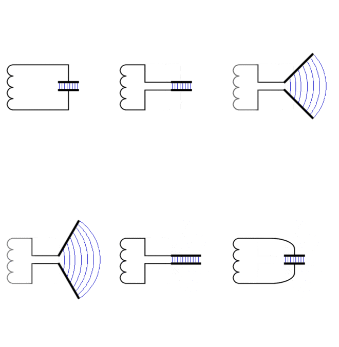
The animation on the right shows how one can imagine the creation of a resonant dipole from an oscillating circuit .
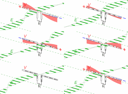
The picture on the right shows the phases of an oscillation of the λ / 2 dipole. Let the electrical excitation start at time zero, when there is the greatest excess of electrons at the left end. At the same time the potential is particularly positive at the right end, there is a lack of electrons. There is no electricity yet.
Opposite charges attract, so many electrons move to the right. A quarter of a period later, at time T / 4, a current maximum is measured in the middle of the dipole, where the strongest magnetic field is created. The voltage across the dipole is balanced at these times.
The magnetic field prevents the current from stopping abruptly. It drives the electrons further to the other side. Exactly half an oscillation period after the start ( T / 2), the electron densities have interchanged and the highest negative voltage is now measured at the right end of the dipole. The electricity has come to a standstill. Now the opposite compensation process starts. After an entire period T , the initial state is restored.
There are two types of dipole:
- It can be divided in the middle to connect a balanced cable. Its impedance must be relatively low (around 70 Ω) for power matching. If an unbalanced coaxial cable is to be used, a balun is required at this point .
- An unbalanced cable with a relatively high impedance (2200 Ω if possible) can be connected to one end of the dipole. If a low-resistance coaxial cable is to be used, a resonance transformer is required at this point to adjust the power ( see also the section on the antenna rod in the article Wave impedance ).
Impedance
The damping of the resonance through the radiation into the free space causes a shift of the resonance to a slightly lower frequency and a complex part of the base point impedance . In the case of a centrally fed open dipole of length λ / 2, this is (73.1 + j 42.5) Ω.
To compensate for the frequency shift and to eliminate the imaginary part, the λ / 2 dipole is shortened by a factor of 0.96. This applies to a dipole that is infinitely thin. But since in reality the diameter of the dipole elements is> 0, the shortening factor decreases further depending on the diameter. Objects near the antenna also increase the shortening factor. The primary cause of the additional shortening is the capacity of the conductor against its surroundings. The bandwidth of a dipole antenna increases with the diameter, which is particularly useful for fan-shaped and broadband dipoles . For the λ / 2 dipole, the shortening factor V results from the dipole length l and the diameter d as:
The folded dipole is also a type of λ / 2 dipole . It is fed in the middle of one of two parallel conductors that are connected to one another at the ends. Its impedance is 4 times higher than that of the stretched λ / 2 dipole, as only half the current flows through the feed points. This goes very well with the balun made of a λ / 2 detour line, which reduces the impedance to 1/4 and enables the connection of a standard coaxial cable.
Directional diagram
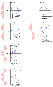
The directional diagram of an antenna , that is the angle dependence of the radiation intensity , can be calculated from the current distribution over the length of the conductor. The expression results from the approximately sinusoidal current distribution on the λ / 2 dipole (top left in the figure on the right)
- ,
where h is the elevation angle for a vertical antenna. For comparison: The corresponding expression of the Hertzian dipole is simply cos ( h ), in the figure to the right. You can see that the radiation of the λ / 2 dipole is a little more directional: The radiated power has already dropped by half at an elevation angle of 39 ° instead of 45 °.
The integration of the angle dependency over all directions provides the total power and its uniform distribution a reference value for the radiation intensity ( isotropic radiator ). For the λ / 2 dipole, the radiation intensity in the main direction ( h = 0) is higher than the reference value by a factor of G = 1.64 (2.15 dBi ). With the Hertzian dipole this antenna gain G is only 1.5 (1.76 dBi). With a length of 5/4 λ the dipole has its greatest gain of 5.2 dBi. Side lobes are formed above this and better values are only possible with a much larger dipole. This is why 5/4 λ dipoles are used as simple directional antennas, especially in the form of ground plane antennas with a length of 5/8 λ. However, impedance matching is essential.
A power-matched antenna draws power from a plane wave incident from the main direction that corresponds to its effective area A W. For the λ / 2 dipole this is:
The directivity of a dipole antenna can be increased by adding further elements, see Yagi antenna .
In cases where the directional effect is just not desired, e.g. B. with desired all-round reception or transmission, you can use a kink dipole , in which the two metal rods are arranged at an angle of 90 ° to each other.
Full wave dipoles
If you place two unpowered half-wave dipoles lengthways next to each other and feed their mutually facing ends, a full-wave dipole is created. There are voltage maxima at the ends of the λ / 2 elements, so full-wave dipoles have a very high supply impedance (> 1 kΩ). An advantage over the half-wave dipole is the slightly improved directional effect and thus an increased antenna gain .
To assemble antennas from two half-wave dipoles and to achieve common cable impedances (around 50 Ω), there are various options:
- The half-wave dipoles are connected to form an array and fed in parallel with the correct phase.
- You change the supply impedance with the help of a resonance transformer .
- You can lower the impedance and at the same time increase the bandwidth if you choose flat dipoles instead of thin rods . Such full-wave dipoles consisting of two triangular surfaces (or equivalent x-shaped rods) are also used as radiators in Yagi antennas. The passive elements of these antennas are dimensioned for the upper part of the frequency bandwidth of the surface dipole, so that the gain increases towards higher frequencies.
A further joining of dipoles is rarely done, because this results in undesirable "side lobes" in the radiation diagram. The antenna then “switches”.
See also
literature
- Martin Gerhard Wegener: Modern radio reception technology. Franzis-Verlag, Munich 1985, ISBN 3-7723-7911-7 .
Web links
- Representation of the wave propagation of a dipole
- Description of voltage-fed and shortened dipoles, special forms pdf 3.5 MB


