The Hertzian dipole (by Heinrich Hertz ), also Elementardipol called, is the idealization of a transmitter of electromagnetic radiation (which is also dipole radiation or Dipolwelle is called) and used to calculate the radiation real antennas as well as a reference antenna , the directivity of an antenna as a gain to be recorded numerically. The multipole radiation (also treated here) results in a generalization.
The Hertzian dipole as a model

Amount of the electric field strength (colored) and the
Poynting vector (black arrows) in the near field of the dipole lying vertically in the image plane. Blue / red colors mean an electrical field oriented downwards / upwards.
Animation of the time and location dependence of the E and H fields in the xy plane
The Hertzian dipole as a model is based on an electrical dipole moment that varies sinusoidally with the angular frequency , represented in complex notation

-
 .
.
Such a pure dipole moment without spatial expansion ( point dipole ) arises in the boundary transition of oscillating charge carriers with vanishing oscillation amplitude ( ) and diverging amount of charge ( ).


Exact equations
The following applies to the magnetic and electric field at the location given by the distance and direction :


-
 ( azimuthal , runs in circles of latitude around the dipole axis)
-
![{\ displaystyle {\ vec {E}} = {\ frac {\ omega ^ {3}} {4 \ pi \ varepsilon c ^ {3}}} \ left [({\ vec {n}} \ times {\ vec {p}}) \ times {\ vec {n}} \, {\ frac {1} {\ rho}} + \ left (3 {\ vec {n}} ({\ vec {n}} \ cdot {\ vec {p}}) - {\ vec {p}} \ right) \ left ({\ frac {1} {\ rho ^ {3}}} - {\ frac {\ mathrm {i}} {\ rho ^ {2}}} \ right) \ right] \ mathrm {e} ^ {\ mathrm {i} (\ rho - \ omega t)} \ quad}](https://wikimedia.org/api/rest_v1/media/math/render/svg/484e0a7482b535553c11fef61477b3b8e155240b) ( Meridional plane or meridional "southward" and radial)
( Meridional plane or meridional "southward" and radial)
In it is
-
 the speed of light
-
 with the wavelength of the radiation.
-
 the absolute permittivity , i.e. in a vacuum . The International System of Units (SI) is used at this point , although the equivalent cgs system simplifies some formulas
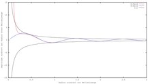
In contrast to all other antenna types, the propagation speeds of the wavefronts can be analytically calculated from these equations for the Hertzian dipole. Overall, the result is a radiation field that has closed field lines at any point in time, with a characteristic kidney shape reproduced in all textbooks (see e.g. the outer field in Figure 1). If you also emphasize the time dependency, you get the above animation, which u. a. the phase velocity , the group velocity and the propagation velocity of the energy in units of the speed of light as a function of the distance to the source in units of the circular wave number . For large distances, all of these speeds approach the speed of light. In the near field , only the speed of signal propagation is correct.


Spherical coordinates with an associated orthogonal base that is dependent on the location
By dividing the fields into the components of the spherical coordinates , the second representation, particularly common in engineering, results. The alignment of the field quickly becomes clear here.
| Radial
|

|

|
| Meridional
|

|

|
| Azimuthal
|

|

|
Near and far range
In the vicinity , dominates because of the term , the electric field, while the magnetic field is negligible: it is approximately in the ratio (r / λ) weaker and in anti-phase to the electric field (that is, when the one field is a maximum, the other has a minimum ). behaves here like a quasi-static (i.e. slowly oscillating) dipole field, and the magnetic field, analogous to a weak inductive impedance in relation to the strong ohmic resistance , is negligible. The magnetic field is perpendicular to the radius vector and the electric field.


The electric field strength is here , angle and frequency dependence correspond to the slowly oscillating dipole moment.
In the long range , , the radius vector and electric field are also nearly orthogonal to each other. Magnetic field and electric field oscillate in phase. Except for constants chosen arbitrarily in the SI system, they have the same functional dependence on the variables. In the cgs system, where these constants are set equal to one, applies (or radiation intensity ).


So that the field lines of the electric field close, there is also a radial component. One term applies to this in the near range and the term dominates in the far range .

Consequences
The last formula has many consequences, including: a. for all radio and television technology . The blue color of the sky is caused by the fact that the sun's radiation stimulates the air molecules to produce dipole radiation. Although the solar spectrum has its maximum in the green spectral range, blue light dominates in the emission (frequencies around the higher value ). The approximate ratio corresponds to almost a doubling of the radiation intensity when changing from a green to a blue frequency with a fixed dipole moment. The formula given is also relevant for mobile telephony, which has become commonplace today . Communication takes place via the dipole radiation emanating from the mobile phone to the nearest switching node, the frequency range ( ) of which is high enough that the signal intensity is sufficient for the transmission of information despite the minimal energy consumption of the mobile phones. At the same time, the frequencies of mobile telephony are still in the biologically harmless range, in contrast to X-rays, for example.


From the far-field approximation to the antenna diagram
In the far field the terms with and are negligible. If we only write down the dominant terms, it follows:


The amount of the common factor contains the directional dependence of the field strength. It varies as with the angle to the equatorial plane and is independent of the azimuth (see adjacent antenna diagram ).


The Poynting vector indicates the energy flux density. Its amount, averaged over time, is in the far field


and apart from one factor equal to the radiation intensity

In this case, the polar angle of the vector measured from is. On the other hand, the result does not depend on the azimuthal angle . The radiation therefore reaches its maximum in the directions perpendicular to that is perpendicular to the antenna. It disappears in the direction of the antenna itself.


If one integrates over all directions, the total power radiated into the far field results
. This result comes from the integration over the solid angle. In the case of isotropic distribution , the radiation intensity would instead be equal to . The ratio referred to as antenna gain is therefore 1.5 (about 1.76 dBi ) in a vacuum .


Generalization: multipole radiation
Definitions
The supply of an alternating current of the angular frequency to an antenna of length thus generates a periodically oscillating electrical dipole vector with the antenna direction (z-direction) as the dipole direction. (The electric dipole moment is where Q (t) is the periodically oscillating electric charge.)


Likewise, a magnetic dipole vector is generated by a particle revolving in the (x, y) -plane on a circle with a radius with the constant charge Q 0 , which by convention also has the z-direction and is circularly polarized according to the direction of rotation. (The magnetic dipole moment is the angular frequency of the revolution .)


Magnetic dipole radiation is therefore an order of magnitude weaker than electrical dipole radiation from the outset because of the quadratic dependence of the moment on the small length (compared to λ) . For these, however, the already known linear relationship applies .
Two slightly offset opposite-equal dipole vectors result in a so-called " quadrupole tensor ", two slightly offset opposite-identical quadrupoles an "octupole" etc. The number of degrees of freedom increases each time by two, not by three, because of the direction of the shift only the two angular coordinates perpendicular to the z-axis are involved.
Instead of the Cartesian coordinates (x, y, z), spherical coordinates are used in the following , which are related to one another in the usual way.

formula
The corresponding generalization of Hertzian dipole radiation is the so-called multipole radiation. Instead of the dipole vector, electric plus magnetic multipole moments or occur, the indices and referring to the polar or azimuthal angle variables or the spherical coordinates . The general formula is after John David Jackson


![{\ displaystyle {\ begin {aligned} {\ vec {E}} ({\ vec {x}}, t) & = \ sum _ {\ ell = 1} ^ {\ infty} \ sum _ {m = - \ ell} ^ {\ ell} \ left [a _ {\ ell m} ^ {(M)} h _ {\ ell} ^ {(1)} (kr) {\ vec {X}} _ {\ ell m} (\ theta, \ varphi) + {\ frac {\ mathrm {i} Z_ {0}} {k}} a _ {\ ell m} ^ {(E)} {\ vec {\ nabla}} \ times (h_ {\ ell} ^ {(1)} (kr) {\ vec {X}} _ {\ ell m} (\ theta, \ varphi)) \ right] \ mathrm {e} ^ {- \ mathrm {i} \ omega t} \\ {\ vec {H}} ({\ vec {x}}, t) & = \ sum _ {\ ell = 1} ^ {\ infty} \ sum _ {m = - \ ell} ^ {\ ell} \ left [a _ {\ ell m} ^ {(E)} h _ {\ ell} ^ {(1)} (kr) {\ vec {X}} _ {\ ell m} (\ theta , \ varphi) - {\ frac {\ mathrm {i}} {kZ_ {0}}} a _ {\ ell m} ^ {(M)} {\ vec {\ nabla}} \ times (h _ {\ ell} ^ {(1)} (kr) {\ vec {X}} _ {\ ell m} (\ theta, \ varphi)) \ right] \ mathrm {e} ^ {- \ mathrm {i} \ omega t} \ end {aligned}}}](https://wikimedia.org/api/rest_v1/media/math/render/svg/64816af16742b6ec173838a70500b228c9f8e60b)
This corresponds approximately to the permutation of and taking into account the sign (+ iZ 0 → i / Z 0 ), analogous to the formal Vertauschungssymmetrie the free Maxwell's equations in the cgs system (vacuum , ):


 is the vacuum impedance which are defined as follows:


with the spherical surface functions and the angular momentum operator .


The weighting factors or describe for electrical or magnetic dipole radiation or for quadrupole radiation , each with different values. So one has three or five values for the consecutive values. In the far range the radial function can be simplified to a spherical Bessel function in accordance with the above formulas. Finally, the quantity k is equal to ω / c .


Near and far field
In the near range the field components are now - with a complicated directional dependency, given by the spherical surface functions - proportional to In the far range, however, all components are still as before and the electric or magnetic fields as well as the radius vector are orthogonal to each other in pairs as with plane electromagnetic waves.


Monopole radiation would correspond. This cannot occur because the external field of a small charged sphere is only given by the constant total charge, regardless of the oscillating sphere radius according to Gauss's theorem . This need not be required as an additional assumption, because in particular is .


See also
literature
- John D. Jackson: Classical Electrodynamics . 3. Edition. deGruyter, 2002, ISBN 3-11-016502-3 .
- Klaus Kark: Antennas and radiation fields: electromagnetic waves on lines, in free space and their radiation. Vieweg, Wiesbaden 2006, ISBN 3-8348-0216-6 .
Web links
References and footnotes
-
↑ a b Dipole moment and antenna length are related to electrical dipole radiation by e.g. B. is approximately set: the dipole oscillating with the frequency ω / (2π) results from the length of the antenna and the opposite charge on the top and bottom .