
Manual input control
A manual input control is a CNC for automated production using machine tools , which is particularly suitable for creating the production program on the machine. One speaks of the “ control ”, which, however, handles control and regulation tasks. The skilled worker should be able to simply type in as large a proportion of his production spectrum as possible without his own calculations. As the values to be entered, the information contained in a clearly dimensioned drawing suitable for production should be sufficient . She therefore needs a lot of aids that enable this even under workshop conditions (volume, lack of space, hazard, etc.). Specifically, this involves functions such as the calculation of the equidistant by the controller, cycles, directly readable program code, graphic simulation, etc.
Programming languages
There are manual input controls that can be operated with 3 different programming languages . A different language can be used in the program and all 3 types can be stored in the same device at the same time. For example, the user can type in a short start program in plain text on the control and call up mass data generated there by the CAM system .
standardization
The standardization uses for the few functions that are regulated so that even with these controls. Here, too, F is the feed rate and the standardized M function M2 z. B. stands for end of program. In the standard DIN 66025 / ISO 6983, usually referred to as DIN / ISO programming for short, basic, but rudimentary specifications are stipulated, which also apply to manual input controls. The other functions are largely manufacturer-specific in structure and mode of operation.
Programming language overview
- Workshop-oriented programming
Language for workshop programming (WOP) supported by text and auxiliary images and other input aids
- DIN-ISO
G-code based programming mainly for external programming. DIN / ISO programs from different control manufacturers are not compatible with one another, because today (2011) every manufacturer interprets the processes that go beyond standardization at their own discretion.
- SmarT-NC (Heidenhain)
From the iTNC 530 onwards, further developed workshop programming with predominant use of cycles for frequent tasks.
"Plain text" -like languages
Many of today's control manufacturers develop and produce one or even several languages of their own. Plain text and images are used, which enable or facilitate workshop programming.
- Plain text
Heidenhain language supported by text and auxiliary images for universal workshop programming
- Shopmill
Development of the German control manufacturer Siemens ( Sinumerik )
- Fanuc
Development of the Japanese control manufacturer Fanuc
- Mazatrol
Development of the Japanese control manufacturer Yamazaki Mazak
Possible uses
Traditionally, the automatic machining production of industrial parts, primarily on lathes or milling machines , but also laser use , bending , water jet cutting , etc. with the special feature that the programs are (can) created by the skilled worker in the workshop. This is especially true for companies with a low division of labor, for small series production with little work preparation . Even with external programming, there is the advantage that processes on the machine can be better assessed than at the programming station and optimized with workshop programming and thus sent back
PLC and NC
Functionally, a numerical control contains 2 fundamentally different areas:
PLC
The PLC (programmable logic controller), and PLC (Programmable Logic Controller = Programmable logic controller) is the current solution for the original hardware-based, fixed wiring. It is developed by the machine manufacturer for a specific machine type and permanently connects current, usually digital input signals and switching commands coming from the NC program by means of logical links.
Example : A travel movement with milling feed is read in the NC program. The PLC checks whether the spindle is turning, the target speed has been reached, the working area is closed and, if necessary, additional safety conditions have been met. Only then, and only as long as all these conditions exist, does it enable the feed. The linking program largely determines the possibilities and comfort of a machine and remains unchanged in standard machines after the machine is delivered. At the customer's request, however, the machine manufacturer can also make changes to the PLC memory after the machine has been delivered. It is not directly visible to the machine user.
NC
The programs in the NC part are used to manufacture the parts currently to be manufactured. In a programming language suitable for the production of parts, they contain instructions for travel commands, cycles for complex production sections, output of switching commands, calculation processes, etc. The programs are created on the machine or externally and can change constantly.
Operating modes
- Setup operation
In the case of manual input control, the NC offers manual operating modes for setting up the machine such as
- Manually,
- Handwheel,
- Manual input (MDI = Manual Data Input)
- Programming station
- Editing mode (creating a program) with screen and data interfaces for creating and
- Operating mode simulation of production programs
- Machine / manufacturing
- Record sequence operating mode for the automatic, continuous production of parts
- Single block operating mode for the line-by-line execution of programs.
Historical development of manual input control
The manual input control has developed from the NC via the CNC.
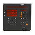
1979 Plain text input, drilling and milling cycles, branching functions. Program display via 1 dialog line (TNC 131, Heidenhain)
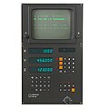
1980 Plain text input, drilling and milling cycles, branching functions. Program display on screen (TNC 135, Heidenhain)

1984 Additional 3D simulation graphics and calculation cycles, parametric functions for creating cycles by the user himself. (TNC 155, Heidenhain)

1989 Additional geometry package with interactive input graphics, colored 3D simulation graphics and plane pivoting. (TNC 415, Heidenhain)
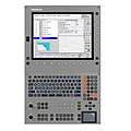
2004 A total of approx. 80 cycles and additional vector graphics to display machining processes with the tool and / or workpiece in a swiveled state, collision monitoring. (iTNC 530, Heidenhain)


(Add other manufacturers!)
developments
CNCs
The availability of microprocessors allowed the construction of CNCs ( Computerized Numerical Controls ) from 1978 . The integrated microcomputer , keyboard and screen, working memory, external storage devices etc. generally made it possible to enter and modify programs on the machine. The microprocessor and computer technology of a CNC allows the manufacturer of machine tools to introduce software improvements and expansions of the functionality into the running machine series without the control hardware - often without having to change the machine mechanics and interconnection. In this way, it is possible to react faster to the requirements of the market. Frequent processes could be defined in a program and developed much more easily. More and more system cycles and finally cycles that the user could create themselves simplified and accelerated programming on site. Ever more powerful electronics also allowed ever more realistic and faster graphic simulation.
Manual input controls
The level of performance of hardware and software, which was reached around 1978, led to the consideration of giving the machine operator / skilled worker access to the production process again in order to use his production knowledge. The creation of the programs had to be simplified to such an extent that it could be managed realistically even under workshop conditions. In a good manual input control, many objectives of the WOP working group are realized (WOP = workshop-oriented programming ). The manual input control offers the user of machine tools new possibilities in the areas of program creation, visualization and operator guidance. At the same time, the performance of controls for external programming was increased by increasing the computing speed, number of axes, interface connection, etc. Today (2011) both manual input controls and controls for external programming are being built. A clear distinction is often not possible, since powerful manual input controls can also be programmed and controlled externally and, on the other hand, many controls that are not explicitly named also have equipment features that are typical for them. Manual input controls are preferred in smaller companies with a low division of labor and in the workshops of large companies.
Performance classes
Performance classes according to the number of simultaneously movable axes:
(1D) Point control
Also known as positioning control. D stands for dimension = machine axes that can be moved simultaneously (at the same time) Can approach specified positions at a fixed, usually maximum speed. The processing takes place at the end point of the movement.
- Tool compensation: Tool length compensation
- Form of movement: straight line movement
- Production types: drilling, sawing, bending, spot welding, laser processing, punching.
(1D) Pattern control
Can traverse 1 axis with a programmable feed rate. The machining can therefore take place during the movement with a suitable feed rate. There is also rapid traverse for positioning.
- Tool compensation: Tool length compensation *
- Form of movement: straight line movement parallel to the axis
- Production types: vertical bores, axially parallel milling patterns, axially parallel weld seams, axially parallel laser processing.
There are controls with an axially parallel tool radius compensation.
(2D) path control
Can traverse 2 axes simultaneously with an interpolated programmable feed rate (so that the programmed end point is reached simultaneously by the axes involved). The machining can therefore take place during the movement with a suitable feed rate. There is also rapid traverse for positioning.
- Tool compensations: tool length compensation and tool radius compensation
- Forms of movement (axially parallel and inclined) straight lines, circles in an interpolation plane, mathematical curves in an interpolation plane.
There is a programmable machining feed rate and a maximum positioning speed.
- Production types: vertical holes, flat milling patterns, bending, welding, laser processing.
(3D) path control
3 Cartesian (perpendicular to each other) machine axes
Can traverse up to 3 axes simultaneously with a vertical tool carrier. There are also 2.5D path controls on the market: 2 of 3 controllable axes can move simultaneously, the 3rd axis must remain in its position during this movement. For other movements, however, it can move in combination with one of the other axes.
- Forms of movement: In addition to the above variants: obliquely arranged, straight surfaces, rotationally symmetrical bodies, spheres (parts), base bodies, regular surfaces.
- Manufacturing types: vertical drilling, milling, bending, welding, laser processing.
(3D) Contour control with additional rigid linear or rotary axes
Can with more than 3 axes simultaneously with the tool or workpiece carrier in a rigid position, calculate the displacement of the tool application point resulting from the control of the additional axes and compensate for it by means of a corresponding compensation movement of the basic axes.
- Tool compensations: Tool length compensation and tool radius compensation, possibly also additive tool offsets for length and radius to take into account tool wear.
- Forms of movement: For obliquely arranged, straight surfaces, (rotationally symmetrical) bodies, spheres (parts), base bodies, regular surfaces and CAD-generated surfaces.
(3D) Path control with additional swiveling linear or rotary axes
Can move with more than 3 axes simultaneously with the swiveling tool carrier and / or workpiece carrier, and calculate the displacement of the tool contact point resulting from the swiveling in and compensate for it by means of a corresponding compensation movement of the basic axes. Can take tool wear into account and allow the operator to change the depth of intervention. Swiveling in to reach machining locations that are difficult to access, to improve the surface quality, improve the cutting conditions, shorter machining times.
- Tool compensations: Tool length compensation and tool radius compensation, possibly also additive tool offsets for length and radius to take into account tool wear. When the tool or workpiece is swiveled in, the compensations take effect in the swiveled plane.
- Forms of movement: For obliquely arranged, straight or twisted surfaces (rotationally symmetrical bodies, spheres (parts), base bodies, regular surfaces).
- Production methods: Inclined drilling, inclined milling, bending, contour welding, contour laser processing.
Program comparison
The following shows the programming of the same task in the programming languages plain text and DIN-ISO of the iTNC 530 (Heidenhain). Contains: Feed (F1000), rapid traverse (F99999 = FMAX = G0), straight line movement (L = G01), circular movement with tangential contour start (CT = G06), center point path (R0 = G40), tool radius-corrected path RL (G41 = left), a drilling cycle (Cycl. 203) and a 3D milling cycle (Cycl. 231).
Plain text
0  BEGIN PGM Format MM
1  BLK FORM 0.1 Z  X+0  Y+0  Z-40
2  BLK FORM 0.2  X+100  Y+100  Z+0
3  L  Z+100 R0 F99999 M3
4  TOOL CALL 5 Z S2000
5  L  X+0  Y+50  Z+2 RL
6  L  Z+0 F200
7  L  X+50  Y+50  Z-10 F1000
8  CT  X+100  Y+100
9  L IY+30 R0
10 L  Z+10 FMAX
11 CYCL DEF 203 UNIVERSAL-BOHREN ~
    Q200=+2    ;SICHERHEITS-ABST. ~
    Q201=-20   ;TIEFE ~
    Q206=+150  ;VORSCHUB TIEFENZ. ~
    Q202=+5    ;ZUSTELL-TIEFE ~
    Q210=+0    ;VERWEILZEIT OBEN ~
    Q203=+0    ;KOOR. OBERFLAECHE ~
    Q204=+50   ;2. SICHERHEITS-ABST. ~
    Q212=+0    ;ABNAHMEBETRAG ~
    Q213=+0    ;ANZ. SPANBRUECHE ~
    Q205=+0    ;MIN. ZUSTELL-TIEFE ~
    Q211=+0    ;VERWEILZEIT UNTEN ~
    Q208=+99999 ;VORSCHUB RUECKZUG ~
    Q256=+0.2  ;RZ BEI SPANBRUCH
12 L  X+20  Y+80 R0 FMAX M99
13 CYCL CALL
14 CYCL DEF 231 REGELFLAECHE ~
    Q225=+0    ;STARTPUNKT 1. ACHSE ~
    Q226=+0    ;STARTPUNKT 2. ACHSE ~
    Q227=-30   ;STARTPUNKT 3. ACHSE ~
    Q228=+100  ;2. PUNKT 1. ACHSE ~
    Q229=+0    ;2. PUNKT 2. ACHSE ~
    Q230=-5    ;2. PUNKT 3. ACHSE ~
    Q231=+100  ;3. PUNKT 1. ACHSE ~
    Q232=+45   ;3. PUNKT 2. ACHSE ~
    Q233=-5    ;3. PUNKT 3. ACHSE ~
    Q234=+0    ;4. PUNKT 1. ACHSE ~
    Q235=+45   ;4. PUNKT 2. ACHSE ~
    Q236=-10   ;4. PUNKT 3. ACHSE ~
    Q240=+20   ;ANZAHL SCHNITTE ~
    Q207=+500  ;VORSCHUB FRAESEN
15 L  X-20  Y+0 R0 FMAX M99
16 L  Z+100 R0 FMAX M30
17 END PGM Format MM
DIN-ISO
%Format G71 *
N10 G30 G17 X+0 Y+0 Z-40*
N20 G31 X+100 Y+100 Z+0*
N30 G01 G90 Z+100 G40 F9999 G17 T5 M3*
N40 G01 X+0 Y+50 Z+2 G41*
N50 G01 Z+0 F200*
N50 G01 X+50 Z-10 Y+50 F1000*
N60 G06 X+100 Y+100*
N70 G01 G91 Y+30 G40*
N70 G00 G90 Z+10*
N40 G203 Q200=+2 Q201=-20 Q206=+150 Q202=+5 Q210=+0 Q203=+0 Q204=+50 Q212=+0 Q213=+0 Q205=+0 Q211=+0 Q208=+99999 Q256=+0.2*
N50 G01 X+20 Y+80 G40 F9999 M99*
N60 G38*
N70 G231 Q225=+0 Q226=+0 Q227=-30 Q228=+100 Q229=+0 Q230=-10 Q231=+100 Q232=+45 Q233=-5 Q234=+0 Q235=+45 Q236=-5 Q240=+20 Q207=+500*
N80 G01 X-10 Y+0 F9999*
N80 G79 M3*
N90 G01 Z+100 F9999 M2*
N99999999 %Format G71 *
Program check and graphic simulation
As soon as the available hardware and software allowed this, test equipment was developed that supported the skilled worker in assessing the self-written program with regard to its functionality and freedom from errors:
- 1982 pure syntax test which detects missing or contradicting information
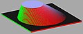
- 1984 graphic simulation for optical control with 3 display modes: top view with gray gradations of the height, crack pattern with 3 sections and 3D display
- 1989 more detailed, faster, color display options, in addition an interactive line graphic for program input
- In 2004, for the first time, a graphic simulation of swiveled machining processes is possible
- In 2006, a programming station from the control manufacturer enables external programming with reliably compatible program code and faster simulation
- 2008 a collision monitoring system to be set up by the machine manufacturer protects against damage to the machine and workpiece, especially in difficult to understand swivel situations
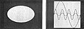
Top view with gray gradations of the height

Crack pattern with 3 cuts

3D illustration
Colored illustration

Simulation of panned processes


hardware
The hardware of a numerical control consists of a logic group, control panel and screen display. There are models on the market in which all 3 components are available separately, as well as variants with a logic unit and display and operating group, as well as complete solutions from a single assembly.
Logic unit
This assembly, which is usually housed in the control cabinet , contains the hardware of the NC and PLC, as well as the interface connections to the machine with control loop connections, signal inputs and outputs and data interfaces.
control panel
The control panel comprises a control part for operating the NC and a machine part for operating the machine. With current controls, the keyboard contains both permanently assigned functions and softkeys (keys whose functions are assigned by displays depending on the situation)
Display unit
With current controls, the display unit contains, in addition to the screen, the keyboard with permanently assigned functions and softkeys.
Control hardware
The various control manufacturers sometimes have their own production-related variants or standard hardware on which, for example, a milling control is emulated by loading the milling software. The hardware of the major NC manufacturers are special developments with digital and / or analog connections for switching input and output signals and the control loops.
PC solutions
There are also PC-based solutions - especially in market niches - with plug-in units for connecting the machine.
Programming by manual input control
In addition to the logic assembly (with memory, interface, control and regulation components, etc.), the device also has a keyboard and screen so that production programs can be entered directly on the machine. In contrast to DIN controls, a manufacturer-specific programming language with mnemonic instructions is used.
Example:
CYCL DEF 1 Tiefbohren
Abstand … Tiefe … Zustellung … Vorschub … Verweilzeit …
The aim of the development is to simplify and support the creation of manufacturing processes directly on the machine to such an extent that the skilled worker can quickly type in all the manufacturing tasks that occur at any time. To achieve this goal, a manufacturer-spanning working group was founded under the keyword WOP.
The program creation directly at the production site by the skilled worker uses his specialist knowledge and the fact that he continuously monitors the progress of production. Only he can observe the subtleties, whether the program is well optimized, the clamping, the work sequence and the selected tool fit. If necessary, he can take corrective action and react to stressful situations and optimize the program sequence and production data.
A special feature is the integration of numerous cycles, which make the execution of frequent processes easier, faster and safer. Depending on the type of machine being controlled, these can be machining processes such as drilling, milling, bending, cutting, measuring processes or pure computing processes. Newer devices have a simulation graphic that allows the production process to be assessed even before machining begins. In addition, the implementation of other functions that support or enable the creation of programs directly in the workshop. This includes a complete geometry package for handling drawings that are not dimensioned in accordance with the NC. (End points, transition points and other dimensions that are required for target-point-oriented programming are missing), and coordinate conversions such as shifting, mirroring, scaling factors, etc. A well-rounded system also includes a programming station that can run on PCs. If you load it with the same machine parameters as for a specific machine, the result is a very realistic simulation.
Current status (2011) for manual input controls
hardware
With the large control manufacturers, logic with PLC and NC in manufacturer-specific hardware. The components are largely up-to-date, highly integrated general-purpose components of the world market. (Note: The development of a new type of controller with the design of hardware and software, tests and production takes time: When a new type of processor is introduced, a delay of the order of 2 years or more must be expected) Semiconductor memory in the high megabyte -Area, permanent storage by hard drives in standard capacities. 32-bit processors in the GHz range, block cycle times under 1 msec (preparation time of an uncorrected 3D linear block). This means that when executing a program in which the positions follow one another at 0.1 mm intervals, a feed rate of 6 m / min can be maintained without stoppages.
Data interfaces
in the order of appearance:
- RS-232 (V.24)
Serial voltage interface has existed since around 1980, at that time transmission rates of 1200 baud (bit per second), today a maximum of 110,000 baud. Common in PCs up to about Pentium 3, but only suitable for short cable lengths.
- RS-422 (V.11)
Serial, fast voltage interface for cable lengths of several hundred meters, requires a separate card in the PC. With a cable length of 100 m, up to 1 Mbaud is possible.
- Ethernet interface
with 1–100 Mbaud
- USB port
0.187 to 60 Mbytes / s
- CompactFlash memory card
8.3 to 167 Mbytes / s
Operator interface

Starting from the punched tape code of the NCs via the mnemonic text code of some CNCs of the 1980s, the input and control of the program was designed more and more clearly:
- A single line of dialog with segment display (from 1979)
- A text screen for program editing (from 1980)
- Graphics-capable monochrome screen and graphics modes for test operation (from 1984)
- Graphics-capable color screen and an additional interactive input graphic (from 1989)
- Right from the start, the iTNC530 had interactive input screens for path functions and cycles, etc., and also had the option of graphically displaying the pivoting of the tool and / or workpiece carrier. Today (2011) also with a separate input help screen for each parameter to be entered.
Programmable functions
Available interpolation types
Linear up to 5 axes simultaneously, circular in the plane, helix , spline
Manufacturing cycles
A large number of cycles with the following functions simplifies and speeds up the programming of machining operations:
- Drilling cycles for simple machining, but also extensively modifiable processes and for extra-long tools,
- Milling cycles for simple pockets, tenons, grooves in round or rectangular shape with selectable immersion strategy (vertical, oscillating, circular), the same for pockets (possibly with embedded islands) each with a programmable outline
- Arrangement cycles for combination with the above chip cycles.
- Coordinate conversions e.g. B. zero offset, (axis-specific) scaling factor, mirroring, rotating in the working plane, three-dimensional swiveling of the tool in a vertical coordinate system, working with a normal tool in a swiveled-in coordinate system, etc.
Duty cycles
Workpiece measurement
Probe cycles for manual or programmed use of a switching probe located in the spindle enable the following measurements on the workpiece: position, length / distance / thickness, angle, for holes or circles, determination of center, radius, storage of setpoints ... and these values are automatically taken into account during the Production of a clamped part. A part only needs to be clamped so precisely that the relevant measuring points are reliably hit. Deviations in position, rotational position and raw dimension tolerances can be measured and taken into account using suitable programming.
Tool measurement
Probe cycles for manual or programmed measurement of the tool clamped in the spindle can measure diameter, length and wear. Wear can be compensated for by corresponding tolerance values in the tool table during parts production or, if limit values are exceeded, the program can be stopped or the replacement of sister tools triggered.
Cutting data
With the help of cutting data tables, feed and speed can be operated depending on the material / cutting material pairing with values suggested by the tool manufacturer or your own experience. With AFC (Adaptive Feed Control = adaptive feed control), the feed rate can be adjusted dynamically during machining and depending on the load and cutting edge wear.
Tables
to manage tool reference points (presets), zero point offsets, pallets, cutting data tables as an "electronic notebook", dynamic optimization of cutting data.
Comprehensive geometry package
for handling drawings that are not dimensioned in accordance with the NC,
Control loop data
Input and control unit 0.1 µm, feeds over 100 m / min, feed programmable in mm per minute, per revolution, time-related, etc.
Special accessibility
Geometry package
In companies with a low division of labor, the programmer often has to deal with drawings that are "not NC-compliant": In plain language this means that the target point cannot be taken directly from the drawing. However, a control system requires a target-oriented position input, i.e.: Drive with a certain path shape (from the current position) to an explicitly specified point x ... y ... Z ....
A drawing can - especially in the case of external orders be designed in such a way that it is geometrically unique, but it cannot be used directly without a specific end point. Calculating intersections, determining tangents, etc. are not typical tasks for skilled workers and can be performed very uneconomically on the machine. Manufacturers of manual input controls relieve the skilled worker of such calculations by enabling other mass inputs than the target point to be entered and the control calculates this itself. The names for this functional complex are - depending on the manufacturer - geometry package, free contour programming (FK), etc. In detail They differ, among other things, in the large number and types of usable information, the number of consecutive freely defined positions, correctability of entered values, usability of program variables, illustration of possible solutions, etc. A good system also finds the required final value from sufficient, consistent information. With this type of position input there are definitely 2, 4 or more geometrically possible solutions from which the programmer has to select the correct one. With consecutive freely defined sentences, the special problem can arise that a completely known target point is not sufficient because the starting point is not resolved.
Actual value transfer
The current position - not known in terms of dimensions - can be transferred to the program at the push of a button and used, for example, as the center of a circle or as a pole for polar coordinates.
Special programming procedures
Program creation in which there are no dimensions that can be entered. The "Programming" and "Manual" or "Handwheel" or "Manual input" modes are active in parallel. Manually approached positions can be transferred into the program semi-automatically as end points of straight line or circular movements or as reference points for production cycles. Typical application: roughing processes, rough recording of curves, where a part does not exist but no exact dimensions. The accuracy of the final result depends on the density of the support points and the care taken in recording and can, if necessary, be improved iteratively with test cuts and subsequent fine corrections of the entered positions.
Playback
Program creation in which there are no dimensions that can be entered. Manually executed movements, including any changing speeds, are continuously transferred to the program as blocks in a selected time grid. Typical application: painting processes. The accuracy can, if necessary, be improved iteratively with further, more successful recordings.
Digitize
Automatic scanning process in which the three-dimensional shape of an existing part or model is approximately captured on a definable path by means of a switching or measuring button or also optically. The process requires a suitable probe system, cycles designed for this purpose and a fast signal input from the controller. This method of creating a program is advantageous when a part or an impression of it exists, but dimensions that cannot be used and when an accuracy of a few hundredths of a millimeter is acceptable. The process had its heyday in the early 1980s. The controls used at the time could only manage the resulting data volumes externally via interfaces. With the introduction of hard disks in the control hierarchy, this was technically possible, but quickly went out of fashion due to rapid advances in CAD / CAM technology.
Well-known manufacturers of manual input controls
- [1] Heidenhain company with TNC
- [2] Siemens ( Sinumerik ) with Shopmill
- [3] Mazak company with Mazatrol
- [4] Fanuc company
- [5] Okuma Company
- [6] General importer for Okuma in Germany
Training and customer support
Programming courses
On-site programming requires well-trained personnel. Manufacturers of controls suitable for manual input therefore offer programming courses. Ideally, this is done first-hand by employees of the manufacturer themselves and in a level and thematically structured course program. Employees of the control manufacturer can respond to other, newer functions at an early stage, because they are right at the source, and because they are intensively involved with the subject, they can even make suggestions for improving the products. It is also common to train multipliers, who pass on their knowledge to vocational schools and other external educational institutions, and to involve the training departments of the machine manufacturers.
Solution collections
Sustainable support for users in solving their manufacturing tasks is as extensive as possible, network-based collection of tried and tested solutions such as a database with suitable NC programs.