Hand embroidery machine

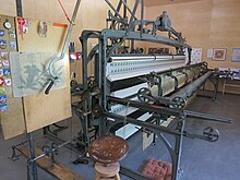
A hand embroidery machine is an embroidery machine that is operated - usually exclusively - with muscle power. A basic distinction is made between single-needle and multi-needle machines. This article deals with the structure of the multi-needle machines as they were used until around 1920.
Terms
Single-needle machines are similar in structure and function to a sewing machine , but chain stitch sewing machines are particularly often used.
By far the most common form of hand embroidery machine was the multi-needle satin stitch hand embroidery machine until around 1900, so called because it could perform the satin stitch with several needles. Because it was so widespread, the satin stitch hand embroidery machine is often referred to simply as a hand embroidery machine. Publications from the time before around 1905 also simply write embroidery machines because there were no alternatives from which one had to distinguish oneself. Unless explicitly mentioned, the term hand embroidery machine in this article refers to a multi-needle satin stitch hand embroidery machine .
history
The concept of the satin stitch hand embroidery machine was invented by Josua Heilmann in 1829. It remained technically as good as unchanged until the end of hand embroidery, although it was not really developed until around 1850 and was produced in large numbers. In the textile industry in eastern Switzerland alone , almost 20,000 hand embroidery machines were used in 1910, most of which were used by home workers in rooms and basements, and around a third in large embroidery factories.
When the Schiffli embroidery machine was ready for the market around 1890 , the hand embroidery machines were gradually displaced. These multi-needle embroidery machines use a shuttle and two threads. Unlike the hand embroidery machines, they can be driven by motors and are around 20 times faster. Your embroidery pattern also resembles the satin stitch, but is actually not one anymore, as it is a two-thread system.
The Schiffli embroidery machines were later replaced by the so-called automatic embroidery machines. They no longer used the pantograph as a model, but a punched tape .
External structure
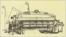
Fig. 1. right shows the external structure of the hand embroidery machine.
- (1) Sample board with attached embroidery template. The sticker sits on the stool in front of it. The half-crouching and half-standing working posture of the sticker was ergonomically very poor and promoted damage to the chest and to health in general. (see section employment relationships in the article St. Gallen embroidery )
- (2) Pantograph for moving the embroidery base (4). The threads with weights running around the ceiling ensure that the arm remains as weak as possible.
- (3) gate, rack
- (4) embroidery base moved using pantograph (2) (the cloth to be embroidered)
- (5) front carriage
- (6) Car transport rail
- (7) Crank to move the carriages
- (8) Transfer device, operated by the sticker with the feet, for transferring the needles
- (9) threading machine. This was invented around 1890 and greatly simplified the threading of the many threads required.
Depending on the type of machine, it had between 200 and 450 needles. The width of the machine varied accordingly. The wider the machine, however, the more difficult it was to operate and the more often work had to be interrupted because needles fell out or threads were torn.
Working principle
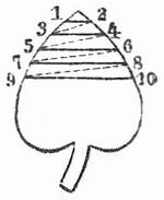
The figures on the fabric are created by inserting the threads with needles through the fabric (old technical term: stuff ) and pulling them through so that they gradually form the desired pattern on the surface. Fig. 2 shows an associated embroidery pattern. The thread follows the course indicated by the numbers 1–10: 1–2 on the front, 2–3 on the back, 3–4 again on the front, and so on.
The embroidery machine mainly consists of a large frame on which the fabric to be embroidered is stretched, the needles and a device that grabs the needle, pierces through the stuff and pulls the thread through it.
With the embroidery machine the frame is hung vertically and movably so that the stuff stays in a vertical plane while the needles only make a horizontal movement through the fabric. So if a needle goes through that stuff in one place, e.g. B. Point 1 of Fig. 2, was pierced, the frame is moved so that the needle when stabbing back the next point, z. B. point 2 of FIG. 2, meets. The embroidery machine works with 200–450 needles, which are distributed in two horizontal rows in such a way that two congruent embroidery can be formed at two different points on the stuff or two witnesses can be embroidered at the same time. To do this, the frame is always moved in parallel. For this purpose, the vertical embroidery frame A (Fig. 3) with two round rails a on rollers b, which sit again in a frame c, which is supported with cutting on the forked end of a lever d, which is shown broken off in FIG is, but in reality continues over the pivot point d 'and at the end carries a counterweight. The counterweights of the levers keep the frame with the rollers e, e1, e2, e3 on it and the spanned stuff in balance. Since the frame is now also guided through vertical slots f at the bottom and through slide rails h and pins g at the top, it can be moved horizontally and vertically without being able to rotate. Two points on the stuff are always shifting parallel and uniformly to one another. Four rollers e, e1, e2, e3 are attached to the frame, into each of which a pawl (e ', e'1, e'2, e'3) engages. Two rollers each (e and e1, e2 and e3) are used to clamp a piece of stuff k, k 'parallel to the frame, while the pawls prevent reverse rotation. Alternatively, a single piece of fabric can be stretched from e to e3, which is then embroidered twice.
When a horizontal row of figures lying next to each other is finished on the embroidery floor, you pull the stuff a little further from e to e1 and from e2 to e3.
The movement between every two needle sticks is transmitted to the frame with the help of a cranesbill ( pantograph ).
Fig. 4 shows the pantograph construction with the movable frame A. I, II, III, IV is a parallelogram rotatable in its corners in hinges . Side II-III is extended to point V, side III to point VI, the dimensions I-VI and II-V being selected so that points V, IV and VI lie on a straight line. Therefore, if point V is fixed and point VI is allowed to circumnavigate the contour of any figure, point IV will describe a similar reduced figure. Point V is rotatably attached to the frame of the embroidery machine, while point IV is connected to frame A. However, since frame A shifts so that every line in it remains parallel in its original position, if point VI is passed along an enlarged figure of the embroidery pattern, every point of the frame, including the stretched out item, will describe the same figure in a reduced size . Most embroidery machines used a reduction factor of six. On the embroidery pattern, the individual thread layers are indicated by lines, the needle stitches by dots, the worker moves a pointed pen attached in VI between every two needle stitches from one point to the next, so that each point of the fabric is shifted a reduced distance in the same direction that corresponds to the real size of the pattern.
The needles used in the embroidery machine have two points and the eye through which the thread is pulled is in the middle. They are pricked back and forth through the stuff by gripping them on each side with pliers, pulling them through, then stabbing them backwards again after moving the frame, releasing them and gripping them and pulling them through with the pliers guided against it on the other side. These tongs sit on each side in two horizontal rows on one each with rollers 1 and 1 'on rails m of the machine frame C against the carriages B, B' to be moved against the stuff. Each frame consists of a wheel frame n n ', the width of the equipment with the attachment points o, o', which bear prismatic rails p, p 'above and below. The pliers are attached to these with their fixed legs q, q ', which have a small plate with a conical hole for inserting the needles on their side facing the stuff . While the needles are in the hole, the movable jaw r, r 'of the pliers is pressed against it in order to hold it in place. This happens in the following way: The “tail” of the movable pliers legs is constantly under the pressure of a closing spring s, s'. Against the other side of the “tail”, however, lies a wave t, t 'which continues over all the tongs in a row and is generally round in cross section and only flattened on one side. If this shaft lies with its round parts on the pincers, they are open; if, on the other hand, it is turned so that its flat side faces the pincers, the “tails” give in to the pressure of the springs and close. To rotate these shafts, the tooth sector u, u 'is used, in which the teeth of a rack v, v' that is moved by a special mechanism engage.
Small, continuous shafts w, w 'are supported on the supports o, o', and levers x, x 'and y, y' are attached to both ends. The ends of the first are each connected by a thin rod z, z 'lying parallel to the stuff, these are placed under the action of the weights β, β' on the embroidery threads and give them an even tension, but are automatically moved away as soon as the Bring the pliers so close to the witness that the levers y, y 'hit the pins ζ, ζ attached to the machine frame. The movement of the carriages n, n 'with the attached tongs is carried out by a worker from one side of the machine by means of a crank turned alternately to the left and right, the movement of which is transferred to an endless chain, the upper run of which is each carried by a carriage connected is.
The machine now works in the following way: one end of the thread may be fastened in the stuff while the other is threaded into the needles. If the left car has just hit the stuff and the needles are pierced with the tips protruding from the pliers, then the right car has to stand in front of the stuff with the pliers open in order to grasp the needles. Then the left pliers are opened and the right pliers closed by actuating the transfer device at the same time via the racks v and v 'by means of the toothed segments u, u' and the shafts t, t ', so that the needles are now held in the right pliers. While the left car remains in its position, the right one moves away from the stuff and takes the needles with it. To do this, the worker turns the large crank. After the carriage has covered a short distance, the small rods y, which can be rotated at w, have slid back so far on the pegs ζ that they have lowered at the same time as the levers x and the crossbars z attached to them under the action of the weight lever β, so that the rods lie on the thread ends that have been pulled through the stuff. The carriage is led so far until the threads are completely pulled out, whereby they receive an even, weak tension through the laid-out rod z, which is sufficient to properly tighten the layer of thread loops just created on the left side of the fabric. Without this tensioning mechanism, when the threads are tensioned, they would often simply be unthreaded from the needles instead of being pulled through the fabric.
Finally the frame A is moved with the help of the cranesbill, then the carriage B is moved back so that z is lifted and the needles are inserted from right to left, whereupon the described process is repeated alternately from left to right.
Problems of the hand embroidery machine and further developments
One of the major drawbacks to this machine was that the threads had to be pulled completely through the fabric with each stitch. As a result, the threads could be as long as the rails, usually a little more than a meter, which, depending on the pattern, was enough for around 250–400 stitches. When the thread is used up, all needles must be replaced with prepared, newly threaded needles. Until the invention of the threading machine (around 1890) threading had to be done by hand and was mostly child or women's labor. Satin stitch machines had between 300 and over 1000 needles, depending on their width. There are reports from the textile industry in eastern Switzerland that the children had to thread needles for 6–8 hours a day, in addition to attending school. In order to be able to use threads of any length instead of short embroidery threads on this satin stitch embroidery machine, mechanics from two- thread sewing machines were later used, and shuttles or hooks were used. These machines are therefore called Schiffli embroidery machines and have gradually replaced the hand embroidery machines, mainly because they could be fully automated. From 1905, automation was completed with the introduction of automatic embroidery machines. Instead of the pantograph, which also had to be guided by the sticker on the Schiffli embroidery machine, they used punch cards .
The embroidery machine as a tool
The hand embroidery machine was seen by the stickers as a tool, not a machine, since without its labor and without its skill it can do exactly nothing. The worker has to follow the pattern exactly and he has to use his muscle power to operate the wheels and levers at exactly the right moment with the right force in order to achieve a good result. His skill is particularly important when pulling the threads through. If it pulls too little, loops form, if it pulls too tight, the threads tear or they unthread. Both provide work stoppages and consequently leads to lower wages because the stickers in the piece rate is paid. Missed stitches and embroidery errors had to be corrected by the (mostly female) embroiderers. These were employed on a time-wage basis and the sticker had to expect deductions from his wages for their work. The sticker also had to use his wages to pay his helper, namely the threading woman - unless she was his wife or his children had to do it. With large machines, two threaders were sometimes employed. In addition to threading the needles, they also had to keep an eye on the machine at all times, because the sticker itself could not always keep an eye on all threads and needles. In particular, those in the lower row were largely hidden from him.
Individual evidence
- ^ Tanner, page 138 and Röhlin, page 51
- ↑ Röhlin, page 41f
- ^ Tanner, 166
- ↑ Tanner, chapter Mentality of Stickers
- ↑ Embroidery Time, page 38
Web links
- Description of the engraving machine invented by Mr. Josua Heilmann in Mulhouse. In: Polytechnisches Journal . 59, 1836, pp. 5-24.
swell
- Embroidery machine . In: Meyers Großes Konversations-Lexikon . 6th edition. Volume 19, Bibliographisches Institut, Leipzig / Vienna 1909, pp. 22-25 .
- Albert Tanner: The boat flies, the engine roars. Weavers, stickers and manufacturers in Eastern Switzerland . Union Publishing House; Zurich 1985; ISBN 3-293-00084-3
- Peter Röllin (concept): The time of embroidery, culture and art in St. Gallen 1870–1930 . VGS Verlagsgemeinschaft, St. Gallen 1989, ISBN 3-7291-1052-7


