
Interrupt
In computer science is meant by interrupt ( English to interrupt "interrupt" by latin interruptus , the participle Passive of interrumpere interrupt) a temporary interruption of a running program, to another, usually short, but time-critical operation to work off.
The triggering event is interrupt request (English interrupt request , IRQ called). Following this request, the leading processor an interrupt routine (even interrupt called English. Interrupt handler , interrupt service routine or short ISR ). The interrupted program is then continued from where it was interrupted.
For example, the keyboard sends an interrupt request when a key is pressed. For this purpose, a signal is applied to the bus or directly to a processor pin ( IRQ input ) that is only intended for this purpose . The interrupt routine can then read the respective character from the keyboard control and forward it to the respective application.
Interrupts are triggered by asynchronous external events. Asynchronous in this context means that the current program is not always interrupted at the same point.
Examples
Other examples where devices generate an interrupt request:
- Network card : when data has been received and is available in the buffer
- Hard disk : when the previously requested data has been read and is ready to be retrieved (reading from the hard disk takes a relatively long time)
- Graphics card : when the current picture has been drawn
- Sound card : if sound data is needed again for playback before the buffer is empty.
history
Older computer models did not have interrupts. The first models with interrupts appeared around 1958, one example being the Electrologica X1 .
purpose
An interrupt is used to be able to react immediately to an input or output (for example from the keyboard, hard disk, network or timer) while another program (e.g. an application) is being processed. The interface hardware only needs to trigger an interrupt if the next operation on the interface (hardware) is not possible, for example if the buffer is empty (output), buffer full (input), if there is error message from the interface hardware or an event without data transfer e.g. timer).
Advantages over polling
In addition to interrupts, there is only the technique of programmed (cyclical) polling to find out the status of input / output devices, processes or other things. Although this method is simpler and does not require any additional hardware, it is much more inefficient than working with interrupts because it uses up the CPU very often. In addition, the speed of response to polling depends on how much time elapses between queries, which can be critical in situations that require an immediate response. With multitasking operating systems, polling is not possible as the only method.
The standard analogy for interrupts in everyday life is a door with a doorbell: While you are doing your tasks, you can be interrupted by the doorbell at any time if a guest wishes to be "processed" and then turn to him. When polling - i.e. without a bell - you would have to run to the door again and again to see whether there were visitors or not. When heating milk, on the other hand, it is probably better not to wait for the "interrupt" of the boiling over, but rather to monitor the process regularly.
Application examples
As an example for an application of interrupts one can imagine a processor which, after it has given a job to a hardware component, does not actively wait for a response (polling), but does other tasks until that hardware component carries it out of its own accord an interrupt draws attention to itself again. Without interrupts, for example, preemptive (= displacing running programs) multitasking operating systems would be impossible, since without them programs could no longer be interrupted, switched over by the operating system (time sharing) and input / output devices could no longer be operated.
functionality
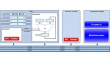
In order to be able to trigger an interrupt, the hardware connected to the main processor ( CPU ) must be interrupt capable , i. In other words, when a certain event occurs, generate an output signal (electrical voltage on an output pin) via the so-called interrupt line . The CPU generally has separate pins for maskable interrupts (INTR) and non-maskable interrupts (NMI). Since the interrupt number must also be transmitted to the CPU for non-maskable interrupts, many systems have an interrupt controller to which this task is delegated if the peripheral device cannot do this itself.
Non-maskable interrupt
When the NMI is triggered, the CPU masks the maskable interrupts and jumps to an address specified by the CPU manufacturer for NMI, which, depending on the computer, is usually in the read-only memory. The ISR stored there usually initiates a restart of the system or global error handling. This depends on the BIOS. Application software has no influence on the behavior when an NMI arrives. The system software cannot prevent an NMI from being handled either.
Maskable interrupt
If a signal ([Vcc]) appears at this pin, which is usually designated as NMI, while interrupts are currently not masked (the interrupt flag (IF) is then set for x86), the CPU masks all maskable I. and reads the number of the requested one Interrupts from the system bus (Intel64 hardware differentiates between 256 interrupt numbers). There the requester must create the number before the request. The CPU then consults the interrupt vector table and takes the address of the associated interrupt service routine from it. This belongs to the driver software of the triggering hardware. When this routine is executed, it must first secure the entire processing context at risk, i.e. the processor registers that it will use. This is followed by the actual handling of the interrupt and finally the restoring of the context and return to the instruction that was last executed before handling the interrupt. When returning, the interrupts are also unmasked. There is a special interrupt return instruction from the CPU instruction set that is used instead of the normal return instruction. Technically, the process corresponds to that of a normal subroutine call with additional handling of interrupt masking.
Software triggered interrupt
With many CPUs, interrupt handling can also be triggered by a CPU command ("INT nn"). This is how individual operating systems implement system calls.
latency
The time between the application of the IRQ signal and the start of the corresponding processing is called latency . For an IRQ with the highest priority, the latency depends primarily on the hardware - with shadow registers the context change can be achieved in one clock cycle - for IRQs with lower priority it depends on the execution time of the preferred interrupt routines. Real-time operating systems are organized and configurable in such a way that real-time requirements can be met more easily and verifiably.
Masking
Interrupt requests can be temporarily ignored by the CPU, for example if another interrupt is being handled. This can be done for certain time-critical and synchronizing routines e.g. B. be necessary in device drivers. This masking applies to all interrupts with the exception of the non-maskable interrupts ( NMI : Non Maskable Interrupt), which are intended for special cases (power failure, hardware failure, etc.), and for the so-called software interrupts that are triggered by a command in a program (e.g. 'int IRQNUMMER' on x86 - this command is used by Linux, for example, to switch from normal applications to kernel mode via system calls ( syscalls ) ).
Asynchronicity
External interrupts ( hardware interrupts ) are basically asynchronous with respect to the interrupted program. that is, the execution of the program is in an indefinite place when the interrupt occurs. Therefore, without special synchronizing measures, interrupts must not have any direct influence on programs (or program variables) or on devices (e.g. hard drives). ISRs are not tasks in the sense of the operating system. For ISRs it should also be pointed out that the interrupt masking may only be canceled (interrupt enable) with special software concepts within the ISR, as both interrupt nesting by external ISRs and a reentrance option for the same interrupt are created.
Some processors know special commands to trigger so-called " software interrupts " from a running task, which apart from the special entry and return conditions act like subprogram calls and are therefore not asynchronous. The same applies to traps that are generated by the CPU in the event of errors (protected access, prohibited instructions (e.g. division by zero), single step debugging, memory management events, but also as a standard interface to operating system calls, etc.) can be triggered themselves and use the same mechanism sensibly.
Interrupt service routines as a programming principle
Particularly in the case of hardware-related event-controlled applications, as are common in embedded systems , a possible approach is to relocate more or less the entire functionality of the system to the interrupt routines or to tasks initiated by them. The processor can typically be put into an energy-saving idle state, from which it wakes up in the event of interrupt requests (i.e. external events). In the extreme case, the main program only consists of an initialization part, which is run through after the system start, followed by an endless loop in which - apart from activating the above. Hibernation - nothing happens.
procedure

In the interrupt cycle of the CPU, the old (interrupted) command counter status (with Intel code segment and instruction pointer) and with some architectures also the status register are saved on the stack . It is now necessary to determine which source triggered the interrupt request. With most CPUs, the source is identified within the interrupt cycle via a value on the data bus, which is usually set by the interrupt controller, thus finding the associated interrupt vector and triggering the jump to the appropriate interrupt routine (ISR). Before or during the ISR, the processed interrupt request (IRQ) must be deleted so that it is not triggered again. In the case of Intel (= PC) -compatible architectures, this is done using input / output instructions within the interrupt routine. So can u. Real IRQs can also be deleted without special measures in the software because of the short runtime until the delete instruction. With some CPU architectures, especially with microcontrollers , there can be several interrupt inputs, whereby the interrupt controller is already integrated here. With simple CPUs only the IRQ and the interrupt cycle take place, whereby the software has to check which source was the trigger and accordingly which routine is to be processed.
If there are several IRQs from several sources by the time of the interrupt cycle, the vector of the most important interrupt request is determined and processed by the hardware (interrupt controller) by means of a selection process. This is followed by the processing of the other pending IRQs.
Basic procedure when an interrupt request occurs (transition from hardware to software):
- As long as either the interrupt input of the CPU or the individual interrupt on the interrupt controller is masked, nothing else happens. Interrupt requests are only accepted after the current instruction has expired. Usually, interrupt requests persist until they are accepted.
- Hardware (interrupt logic of the interrupt controller) determines the interrupt vector of the activated IRQ with the highest priority, which is not masked.
- The CPU accepts the interrupt request and executes the interrupt cycle during which (depending on the CPU) the interrupt vector is read from the data bus. The interrupt input is then automatically masked and thus blocked, so that not any number of nested interrupt sequences can occur and cause the stack to overflow.
- In the interrupt cycle of the CPU, the old (interrupted) command counter status (with x86 code segment cs and instruction pointer eip ) and with some architectures also the status register are saved on the stack . The new command count is read from certain memory locations or from an interrupt table, the index of which is determined from the interrupt vector. In the latter case, however, the vectors themselves do not represent the indirect entry addresses.
- The software of the interrupt service routine (ISR) starts and must first copy the contents of all registers that it will use itself (possibly also the status register if it was not automatically saved) onto the stack, otherwise the data of the interrupted Tasks cannot be restored. (If mistakes are made in the process, this leads to random error effects in foreign programs that are difficult to track!)
- The actual interrupt service routine is now running. Depending on the task, z. B. input and / or output data buffered z. B. in a ring buffer ; Time references are usually lost here, but not sequences. If necessary, after a special operating system function has been called by the ISR, a corresponding task can be started (woken up) by the scheduler of the operating system. Since this takes some time, the same interrupt may occur again in the meantime, which must be taken into account in the ISR algorithm if the interrupts are not masked anyway.
- The ISR software restores all the registers it has backed up.
- The ISR terminates with a return jump ( RTI ), which causes the old command counter and, if applicable, the old status register to be saved from the stack and which is then as it was before the interruption (as if nothing had happened). By restoring the status register (which also contains the interrupt mask bit), the interrupt logic is immediately ready to accept further IRQs.
- The called task can now take over further processing of the buffered data.
Categorization of interrupts
A distinction is made between precise interrupts and imprecise interrupts. Precise interrupts keep the machine in a well-defined state, imprecise not.
A software interrupt is a program command that has the same effect as a hardware interrupt; one speaks of an explicit interrupt request. A hardware interrupt, on the other hand, is initiated externally to the processor via an IRQ channel or pin.
A distinction is also made between interrupts according to their trigger:
- The input / output devices can send a signal that they have finished their task or that they have had an error.
- The program can trigger an interrupt by arithmetic overflow , dividing by zero, an attempt to execute unauthorized machine code, or a reference to a target outside the permitted range. In this case, a processor-internal error detection is triggered and activates the interrupt on processor-internal, but purely hardware-related signal paths.
- The timer allows the operating system to perform tasks regularly. To do this, running programs are interrupted. For example, a timer can be built into the processor or it can be present as an external module; in both cases, its expiration acts like an input / output event.
Another difference is the implementation on the signal processing level:
- In the case of level-sensitive interrupts, the processor reacts continuously to an interrupt signal as long as its intended logic level is present, active high and active low are possible implementations.
- In the case of edge-sensitive interrupts, the event is indicated by the change in the logic level itself and then held by the processor for a specified period of time; a few clock cycles are normal.
Processor interrupts are also known as exceptions and can be divided into three types:
- Aborts are very important errors, e.g. B. hardware failure,
- Faults occur before an instruction is completed,
- Traps occur after a statement has been completed (used when debugging).
Hardware example x86 architecture
All Intel processors have an interrupt signal input for maskable interrupts. In order to be able to connect several interrupt sources, there is a separate interrupt controller component (e.g. the programmable interrupt controller , PIC), which has several interrupt inputs and merges them into one signal. In addition, it can be configured using internal registers so that, depending on the interrupt triggered in the CPU interrupt cycle, it places various predefined interrupt vectors on the bus , which the CPU then reads in. With newer processors, all of these functionalities are integrated into the core of the main processor .
256 different interrupt vectors are possible with x86 processors. The interrupt vector is read from the data bus as an 8-bit value in the interrupt cycle of the processor. With x86 processors, the vectors themselves are not the indirect entry addresses. Rather, the vector is multiplied by 4 in real mode (binary shifting) so that 32-bit jump addresses can be accommodated for each vector, to which the jump is then made. In protected mode, it is multiplied by 8 because a descriptor entry is 8 bytes long. In real mode , the interrupt table is in the first kilobyte of the main memory (0000h: 0000h-0000h: 03FFh). Each interrupt number requires 4 bytes: 2 bytes for the code segment and 2 for the offset within the segment. In the protected mode of the CPU, the position of the table is determined by the interrupt descriptor table. For each interrupt, 8 bytes are required for the descriptor entry of the ISR.
In modern systems (e.g. PCI systems), several devices can usually share an interrupt input (called interrupt sharing ). The handling routine for such an interrupt must then call all drivers whose devices could have triggered this interrupt (this cannot be determined at the IRQ). Problems can arise if individual drivers are active for too long, and in the meantime in the device that originally triggered the interrupt, for example, the buffer becomes full and overflows. In the worst case, this leads to data loss.
With modern peripheral devices, the computer and the operating system themselves assign the IRQ numbers (PnP = plug-and-play devices); while with old plug-in cards, for example with ISA cards, the IRQ inputs have to be set manually or are permanently wired to the cards.
Under Linux you can query the interrupts with the following command:cat /proc/interrupts
Under Windows (XP and newer) you can query the interrupts with the following command: msinfo32.exe→ Hardware resources → IRQs
| IRQ | use |
|---|---|
| 0 | System clock |
| 1 | keyboard |
| 2 | Cascaded to IRQ 9 (for 8–15) |
| 3 | COM 2, 4, 6, 8 (EIA-232 / RS-232 ) |
| 4th | COM 1, 3, 5, 7 |
| 5 | LPT 2 ( IEEE 1284 ) or sound card |
| 6th | Floppy disk drive (floppy) |
| 7th | LPT 1 |
| 8th | Real time clock (RTC) |
| 9 | Redirected to IRQ 2 (but also VGA and NIC , IRQ 16–23) |
| 10 | Free PCI bus if necessary |
| 11 | Free Adaptec SCSI if necessary |
| 12 | PS / 2 (mouse, other input devices) |
| 13 | Math coprocessor (FPU) |
| 14th | Primary IDE or ATA |
| 15th | Secondary IDE or ATA |
See also
Web links
Individual evidence
- ↑ a b A. Metzlar: BIOS. The practice book. Franzis, 2004, ISBN 978-3-7723-6706-9 , p. 379.
- ↑ A. Tanenbaum : Modern operating systems. Pearson Studium, 2009, ISBN 978-3-8273-7342-7 , p. 406.
- ^ W. Stallings: Operating Systems: Internals and Design Principles. Prentice Hall International, 2000, ISBN 978-0-13-031999-9 , p. 136.
- ^ W. Stallings: Operating Systems: Internals and Design Principles. Prentice Hall International, 2000, ISBN 978-0-13-031999-9 , p. 62.
- ^ EW Dijkstra : My recollection of operating system design . (PDF) EWD 1303, 2000, p. 15
- ↑ A. Tanenbaum : Modern operating systems. Pearson Studium, 2009, ISBN 978-3-8273-7342-7 , p. 109.
- ^ W. Stallings: Operating Systems: Internals and Design Principles. Prentice Hall International, 2000, ISBN 978-0-13-031999-9 , p. 17.
- ↑ A. Metzlar: BIOS. The practice book. Franzis, 2004, ISBN 978-3-7723-6706-9 , p. 85.