
Joule cycle
The Joule cycle or Brayton cycle is a thermodynamic cycle that is named after James Prescott Joule or George Brayton . The clockwise process is a comparison process for the process occurring in gas turbines and jet engines and consists of two isentropic and two isobaric changes in state . As a counter-clockwise process, it is also suitable for heat pumps or refrigeration systems.
description
- Outline sketch and state diagrams

Mechanical implementation of the closed Joule process

Joule process in the pv diagram

Joule process in the Ts diagram


The four process steps are in detail:
- 1 - 2 isentropic compression (dp> 0, dQ = 0, dv <0),
- With adiabatic compressors
- Supply of compressor work
- Pressure is increasing on
- Temperature rises of at
- Specific volume decreases from on
- Specific entropy remains constant
- 2 - 3 isobaric heat supply (dp = 0, dQ> 0, dv> 0),
- Through heat exchanger (combustion chamber)
- Supply of specific heat
- Pressure remains constant
- Temperature rises of at
- Specific volume is increasing on
- Specific entropy increases from to
- 3 - 4 isentropic expansion (dp <0, dQ = 0, dv> 0),
- By adiabatic turbine
- Withdrawal of turbine work
- Pressure drops from on
- Temperature drops from on
- Specific volume is increasing on
- Specific entropy remains constant
- 4 - 1 isobaric heat dissipation (dp = 0, dQ <0, dv <0).
- Through heat exchanger (cooler)
- Withdrawal of specific heat
- Pressure remains constant
- Temperature drops from on
- Specific volume decreases from on
- Specific entropy sinks from on


Graphically shown in the Ts diagram, the heat supplied is the area enclosed by the isobars between 2 and 3 and the x-axis. The dissipated heat corresponds to the area between the isobars from 4 to 1 and also the x-axis.

The area enclosed by the line (1 - 2 - 3 - 4) corresponds to the specific process work w ( w = - ).
In contrast to the closed Joule process, there is no cooling in the open one, as cold gas is continuously sucked in and compressed.
The supply of heat, which is only shown schematically here, is actually achieved by burning a mostly fossil fuel. For this purpose, jet engines usually use kerosene , which is an intermediate fraction of petrol and diesel in the distillation of crude oil.
The following figures show true-to-scale diagrams and a table with the state variables and process data from a computationally active file.
- State diagrams and data table

pv diagram

Ts diagram
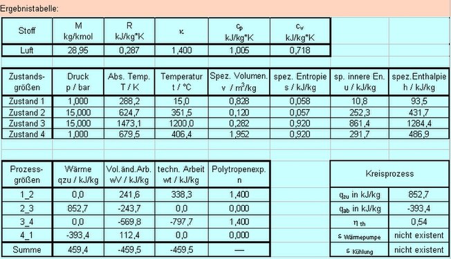
Data table


Efficiency
Efficiency in the single-stage Joule cycle
In general, the thermal efficiency is defined as the ratio of benefit to expense.

In the Joule process, the benefit consists in the technical work w benefit , the effort consists in the required heat q zu , so that we can formulate:

The balanced heat is replaced by the enthalpy differences.


For an ideal gas , the specific enthalpy h is only a function of the temperature and is independent of the pressure.

Therefore

The last relationship results from using the equation for the temperature change in isentropic compression.


The isentropic exponent under normal conditions for noble gases such as helium and argon is approx. 1.66; for 2-atom gases such as hydrogen, oxygen and air approx. 1.4 and for 3-atom gases with rigid molecules such as water vapor approx. 1.33. Cycle processes can be operated most effectively with noble gases. However, if the heat capacity, the thermal conductivity, the heat transfer coefficient and the viscosity are also taken into account, then hydrogen is also a very advantageous working medium.

For a maximum temperature T 3 given by the material , an optimal temperature T 2 can be determined after compression, at which the cyclic process produces the greatest possible useful work:

Possibility of increasing the efficiency through recuperative heat transfer and through a multi-stage Joule cycle
Since the temperature at the outlet of the expansion machine is usually above the temperature at the outlet of the compressor, a heat exchanger can be used for recuperative heat transfer. This amount of heat then does not have to be supplied from outside. In addition, the temperature difference to be bridged between heater and cooler can be increased.
The efficiency is then calculated as follows:

The compression work can be reduced by a multi-stage compression with subsequent heat dissipation, just as the relaxation work can be increased by multi-stage expansion with the respective supply of heat, which increases the efficiency of the overall process. With an infinite number of compression stages - heat dissipation, the process changes to isothermal compression. The process is then described by the Ackeret-Keller or Ericsson cycle , the efficiency of which is calculated analogously to the Carnot process:

Low-maintenance heat engines based on the Joule cycle
Like a Stirling heat engine, a heat engine can be operated according to the Joule cycle with an external heat supply and thus has many advantages in common with a Stirling engine.
Turbocompressors for helium have been developed for nuclear technology (nuclear power plants), which can be equipped with magnetic bearings and permanent magnetic emergency bearings, so that no liquids such as lubricating oils, which can contaminate the gas cycle, have to be introduced into the working gas.
A gas turbine is therefore conceivable that works according to the Joule cycle as a comparison process with helium or hydrogen as the working gas, which could be low-maintenance, efficient and have a high energy density.
The real gas turbine process

The real gas turbine process differs from the theoretical Joule process due to the irreversibility of the technical changes in state (1-2, 3-4). In addition, pressure losses occur in the combustion chamber (2-3) (or the heat exchanger 4-1 in the closed gas turbine process). The pressure change caused by the heat losses in the combustion chamber can nowadays be minimized by suitable measures (high-temperature-resistant ceramic), while the pressure loss in the heat exchanger (4-1) can only be reduced to a limited extent. The mentioned differences can be clearly shown in the Ts diagram (T temperature, s-specific entropy).
The technical work for the compressor and the turbine is illustrated in the h, s diagram (h-specific enthalpy, s-specific entropy).
Other comparison processes
Web links
Individual evidence
- ^ Thermodynamics 2. Accessed July 12, 2017 .