
Cable ladder

A cable tray (also called a cable tray ) is a supporting body for cables and electrical lines . Cable racks are usually made of folded steel, stainless steel sheet or halogen-free polyester ( extruded glass fiber reinforced plastic (GRP)) and are attached to the ceiling or wall using a support arm. The platform is perforated or slotted for fastening with screws and nuts on the support arm, which also reduces the weight and enables a certain view from below. Cable racks can be closed with a cover or clamp. Cables can be organized and fixed in the platform with cable ties .
Use of cable trays
Cable racks are mainly used for large amounts of cables, as found in large buildings. They allow cables to be laid after the flatbed has been assembled by laying the cables in it. This makes it easier to expand the electrical system later or to replace the cables.
To determine the permissible current carrying capacity of cables and lines, the reference installation type E must be used as a basis when they are laid on cable racks and the reference installation type F or G according to DIN VDE 0298-4 for single-core cables and lines. This standard applies in particular to bundling (bundling) of cables on cable racks.
Function maintenance
A cable system in escape routes , necessary corridors and stairwells is required to maintain functionality in the event of a fire in order to ensure the functionality of the connected devices such as fire brigade elevators and sprinklers . In particular, there must be no short circuit or power interruption. This is to ensure safe exit from the building.
Function maintenance is formulated in exactly the opposite way for escape routes. There it should be ensured that escape is possible within a defined period of time without interference from cable systems such as cable racks. This is usually done by removing the equipment (cladding with fire protection panels).
The maintenance of functions is based on the model line system guidelines (MLAR of November 17, 2005) and the country-specific line system guidelines. Laying types are named there that guarantee that electrical cable systems function properly:
- Lines according to the test requirements of DIN 4102-12
- Lines on bare ceilings, covered with at least 30 mm screed
- Lines that are laid in the ground.
For cable racks, DIN 4102-12: 1998-11 describes the so-called "standard support system":
- Distance between supports: SV 1200 mm / AV 1500 mm
- Second suspension: in the area of the bracket ends, i.e. H. additional threaded rods as a second suspension
- Width of the perforated cable tray: 600 mm
- Sheet thickness: 1.5–2.5 mm
- Side height: 60–110 mm
Depending on the prescribed duration of the functional maintenance, the standards are E30 (functional maintenance at least 30 minutes) to E90 for the cable systems (cables and trays) or I30 to I90 for the removal of the cable trays in escape routes, necessary corridors, stairwells and escape routes.
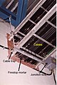
Cable tray opening with bulkhead

Platform opening without bulkhead

Platform breakthrough with improper DIN4102-B3 (highly inflammable) polyurethane foam bulkhead in a paper mill in Ontario, Canada

Cable tray breakthrough in the fire test according to DIN 4102

Cable lines on trays


literature
- Hans-Günter Boy, Uwe Dunkhase: Electrical installation technology The master's examination . 12th edition, Vogel Buchverlag, Oldenburg and Würzburg 2007, ISBN 978-3-8343-3079-6
- Alfred Hösl, Roland Ayx, Hans Werner Busch: The electrical installation in accordance with regulations, residential construction, commercial industry . 18th edition, Hüthig Verlag, Heidelberg 2003, ISBN 3-7785-2909-9
Web links
- Electric line systems. (PDF; 1.2 MB) Guidelines for damage prevention. In: VdS 2025. VdS Verlag, January 2008, accessed on May 8, 2012 .