Small signal behavior
The small signal behavior describes the behavior of a system when modulating with small signals, whereby the word "small" is not to be understood as a short distance to the zero point , but to an operating point . In a non-linear relationship between input and output signals, signals are referred to as small signals, as long as the transmission behavior is approximately linear in a restricted but essential area for the task.
This behavior is in contrast to the large-signal behavior over the entire possible or technically sensible dynamic range. The addition “large signal” in the behavior is characteristic that the non-linearity in the transmission behavior can no longer be neglected. A mathematical description of the non-linear system behavior is required to deal with the large-signal modulation. An alternative to determining the transmission behavior - for particularly complex functions - is a graphical solution. Characteristic curves also help to illustrate the behavior and the control limits.
The linearity approximated by the small-signal operation is a prerequisite for the application of the Laplace transformation for system analysis in systems theory / electrical engineering .
field of use
The description by means of the small-signal behavior is applied in electronics to the transmission behavior of non-linear components and analog-electronic circuits that contain transistors or other non-linear semiconductor components. It is also used in control engineering for the transmission behavior of controlled systems.
The respective operating point is selected so that neither the limits of the modulation range nor more non-linear areas of the transfer characteristic are reached. A small modulation around the operating point results in an approximately linear relationship between the input and output variables.
Any non-linearity creates distortion . Harmonics arise , which is synonymous with an increase in the distortion factor . The limit for the small-signal behavior results from the limit to how far the distortion can be accepted.
Linear approximation
A continuously curved characteristic and its tangent at an arbitrarily selected operating point match at this point in terms of the function value and the increase. In the vicinity of the working point, the agreement still applies approximately. Then the tangent can serve as a linear approximation . It is represented by a linear function , the mathematical treatment of which is easier than that of the characteristic curve. The behavior of a system in the context of the linear approximation is its small-signal behavior.
The procedure is called linearization . A nonlinear smooth function can be represented by a Taylor series . In the area of the linear approximation, the series that is developed at the operating point can be broken off after the linear term. The links up to the point of interruption in the series are the mathematical representation of the linear approximation.
If is at the working point , then the equation is
It stands for the differential quotient of at the point and clearly for the increase.
The distance up to which the linear approximation is permissible from the operating point depends on the accuracy requirements. In particular, the approximation is suitable in practice if the amount of the deviation of the tangent from the characteristic is of the order of magnitude of the deviations in the measured values and the tolerances of the parameters.
If the function is not known, but individual points on the characteristic are known (e.g. table values), then a straight line connection between two points that corresponds to a secant is used as a linear approximation. In scattering readings to a linear model function can be a best-fit line calculated.
- Example diode
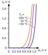
The current-voltage characteristic of a silicon semiconductor diode in the pass band (for the diode current with positive voltage ) can essentially be described by the Shockley equation .
For the non-linear function , the linear approximation at operating point A results from the Taylor approach with the operating point coordinates and
and after inserting and differentiating
For the small-signal quantities and becomes
The small-signal behavior of a diode thus corresponds to that of a differential resistor , the value of which is inversely proportional to the current strength at the operating point.
- Example varistor
In the breakdown area, the characteristic curve of the varistor is approximated by
with and . For zinc oxide varistors is typically in the range 30 ... 70. The differential resistance results from
This means that the small-signal resistance is around one and a half to two powers of ten smaller than the large-signal resistance at every operating point in the breakdown range.
literature
- Ulrich Tietze, Christoph Schenk: Semiconductor circuit technology . 12th edition. Springer, Berlin 2002, ISBN 978-3-540-42849-7 .
Individual evidence
- ↑ Wolfgang Reinhold: Electronic circuit technology: Basics of analog electronics. Hanser, 2nd ed., 2017, p. 47
- ↑ a b Dietrich Naunin: Introduction to Network Theory: Calculating the steady and dynamic behavior of electrical networks. Vieweg, 1985, 2nd ed., P. 21
- ↑ Horst Gad, Hans Fricke: Basics of the amplifier. Teubner, 1983, p. 27
- ↑ Manfred Stockhausen: Mathematical treatment of scientific problems: Part 2. Steinkopff, 1980, p. 1
- ↑ Matthias Plaue, Mike Scherfner: Mathematics for Bachelor's Degree: basics, linear algebra and analysis. Spektrum Akademischer Verlag, 2009, p. 203
- ↑ Michael Oberguggenberger, Alexander Ostermann: Analysis for computer scientists: Fundamentals, methods, algorithms. Springer, 2nd ed., 2009, p. 144
- ^ Adolf Riede: Mathematics for biologists: A basic lecture. Vieweg, 1993, p. 105.
- ↑ Eberhard Zeidler (ed.): Teubner-Taschenbuch der Mathematik. Teubner, 2nd ed., 2003, p. 667
- ↑ Bodo Runzheimer: Linear planning calculation and network planning technology. Springer, 2nd ed., 1983, pp. 205 f


