Differential resistance
For resistors and other two-pole passive electrical components for which a time-independent voltage can be specified based on a current strength , the physical quantity electrical resistance is defined as the ratio of voltage to current strength. In addition, the differential resistance is defined as the change in voltage in relation to an associated (differentially) small change in the current intensity. These components have a characteristic that goes through its zero point in a Cartesian coordinate system. In the idealization of an ohmic resistance , this characteristic curve is a straight line, and the electrical resistance is a constant that applies to any current strength. For the other passive components, resistance and differential resistance can be different at each point on the characteristic curve.
Two-pole components whose characteristics do not go through the zero point are energy sources . Their behavior is usually described using an equivalent circuit consisting of an ideal current or voltage source and passive components with their properties.
The differential resistance can be measured or calculated from the derivation of the characteristic curve at the desired point. It is used to describe the small-signal behavior of components.
Linear resistance
For some materials, such as metals, it is a good approximation that if the voltage is increased by any factor α , the current strength also increases by the same factor α . Then is the quotient
the same for all measuring points and is called linear resistance . In this case, there is no difference between resistance and differential resistance. If the equation applies to any instantaneous values , the quotient is also called ohmic resistance .
Non-linear resistance
In the case of a non-linear voltage-current characteristic curve, the quotient for a voltage-current value pair is different at each point, which is why it is not possible to specify a value in a closed manner. In a sub-area in which the characteristic curve runs approximately in a straight line, the quotient , which is formed from small changes in values , is almost the same at every point; thus it can be specified for the area. This quotient at the selected “ working point ” A of the characteristic curve is the differential resistance for the range. It is illustrated in the adjacent diagram in the slope of the tangent.
In the vicinity of this point, the behavior of a component can often be described by its small-signal equivalent circuit with linear components. If a small alternating current is superimposed on a direct current (or equivalent: if a small alternating voltage is superimposed on a direct voltage), the differential resistance for the alternating quantities is also referred to as alternating current resistance or as dynamic resistance . The resistance illustrated by the straight line through the origin is accordingly also called direct current resistance or static resistance .
Calculation of the differential resistance
If a function can be specified with sufficient accuracy, the differential resistance can be calculated using the differential quotient:
If, for example, the Shockley equation applies to a diode when it is operated in the forward direction , its AC resistance can be calculated from this , with the quantities in the numerator being constants. Since there is usually no such functional relationship, the following can only be calculated from the differences between neighboring measured value pairs and :
When selecting the pairs of measured values, please note:
- If their distance is too great, the rise of a tangent is not calculated, but that of a secant.
- If their distance is too small, the unavoidable measurement deviations cause unrealistic fluctuations in neighboring quotients. It is not possible to create a limit value with discrete measured values.
The experimental determination is shown using the example of a Zener diode :
- The current through the Zener diode should be measured between the connections.
- Measure the current through the Zener diode .
From this it can be calculated - a value that is considerably lower than the quotient from each pair of measured values. This low differential resistance explains why Zener diodes are used for voltage stabilization: Although the current strength quadruples, the voltage only changes by 2%.
Note: To calculate the thermal load of a Zener diode, the (far too small) differential resistance must not be used in the formula ; rather, the mean direct current resistance is used to calculate this.
Positive differential resistance
With positive differential resistances, the current strength increases with increasing voltage. Most elements in circuit technology have an exclusively positive differential resistance. For example, this also includes thermistors , non-specialized diodes in the sense of a pn junction and npn transistors in the output characteristic field with constant control.
Negative differential resistance
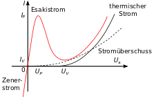
The differential resistance can be negative in a part of the characteristic curve, so that the current intensity decreases with increasing voltage or the current intensity increases with decreasing voltage. In the picture for the tunnel diode, this is the case in the area . A negative differential resistance can be used to excite (de-dampen) resonant circuits or to generate relaxation oscillations in order to build an oscillator . In the early days of radio technology, for example, powerful arc transmitters were built. The negative differential resistance also occurs with gas discharges or with components such as avalanche and tunnel diodes and diacs , in simple electronic circuits such as the lambda diode , but also with more complex modules such as e.g. B. Switching power supplies on the input side.
If a glow lamp is operated in such a way that the voltage rises from zero and exceeds the "switchover point" A, at which the negative differential resistance begins, the switchover to the other state B takes place very quickly. If the current is not limited, the component will be destroyed. For this reason, gas discharge tubes must always be operated with a series resistor.
The switching time is determined by the internal capacity and the type of charge carrier:
- With a gas discharge, relatively heavy ions have to be moved a few millimeters, which is why the switching time is in the range of 10 −6 s.
- In a tunnel diode, electrons that are considerably lighter are only moved a few micrometers above the barrier layers, which is why the switching time is in the range of 10 −11 s.
In the case of components with partially falling characteristics, a distinction is made between two basic types, depending on their shape and thus their stability behavior, which have a significant influence on the external circuitry:
- Arc-type characteristics are S-shaped. Since a certain voltage is clearly assigned to the current, it is also called current-controlled or idle-stable. They occur, for example, with electric arcs and glow discharges .
- Dynatron type characteristics are N-shaped. Since a certain current is clearly assigned to the voltage, they are also called voltage-controlled or short-circuit-proof. They occur, for example, with the Dynatron and the tunnel diode.
Applications
- If a differential resistance of typical is specified for a Zener diode with and in the data sheet , a voltage increase of 30 mV (≈ ½%) causes a current increase of typically 2 mA (40%). The DC resistance (in the example ) is considerably greater than the differential resistance.
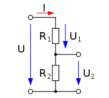
- If an alternating voltage is rectified and smoothed with a capacitor, the direct voltage shown on the right is created with a superimposed smaller alternating voltage ( residual ripple ). In the voltage divider shown below, this Zener diode is replaced and fixed. Then the voltage divider behaves like for the DC voltage, and like for the AC voltage , whereby the AC voltage component is divided down more than the DC voltage component in a ratio of around 1:35. This serves a further smoothing.
- If the frequency is high enough, pin diodes can be used as DC-controlled AC voltage resistors with a short response time.
- In the reverse direction, only the very low junction capacitance around 1 pF allows little alternating current to pass.
- In the forward direction, the superimposed alternating current is only slightly attenuated by the low differential resistance of around 1 Ω.
- If the forward current is reduced, the pin diode acts like a variable resistor with which controllable attenuators can be built.
See also
literature
- Ralf Kories, Heinz Schmidt-Walter: Pocket book of electrical engineering . 6th edition. Harri Deutsch, 2004, ISBN 3-8171-1734-5 , pp. 320-321 .
Individual evidence
- ^ A b Erwin Böhmer, Dietmar Ehrhardt, Wolfgang Oberschelp: Elements of applied electronics: Compendium for training and occupation. Vieweg and Teubner, 16th ed., 2010, pp. 6, 7
- ^ Rainer Ose: Electrical engineering for engineers: Fundamentals. Hanser, 5th ed., 2014, p. 21
- ↑ Wilfried Plaßmann, Detlef Schulz (Hrsg.): Handbook of electrical engineering: Basics and applications for electrical engineers . Vieweg + Teubner, 5th ed., 2009, p. 394
- ↑ Eugen Philippow : Nonlinear electrical engineering (= library of high frequency technology . Volume 12 ). Academic publishing company Geest & Portig K.-G., Leipzig 1963, DNB 453767486 .
- ^ Wilfried Weißgerber: Electrical engineering for engineers 1: DC technology and electromagnetic field . Springer Vieweg, 10th ed., 2015, p. 17
- ↑ H. Frohne, KH. Locher, H. Müller, T. Harrieshausen, D. Schwarzenau: Moeller basics of electrical engineering . Vieweg + Teubner, 21st edition, 2008, p. 33
- ^ Herbert Bernstein: Analog, digital and virtual measurement technology . Oldenbourg, 2013, p. 226
- ↑ Franz-Heinrich Lange: Signals and Systems . tape 2 . Verlag Technik, Berlin 1968.


