
Knapsack circuit


As a knapsack circuit a special connection type of electrodes is reducing , three-phase - arc and ladle furnaces called. This type of connection enables efficient cable routing between furnace transformer and electric furnace, in which the effect of the reactive components of the individual conductors is minimized. The circuit was first used in 1924 in the Knapsack Chemical Park for a carbide furnace .
General
Arc, ladle and reduction furnaces are operated at voltages in the range from a few hundred to over a thousand volts. Due to the high power of a few MVA to over 300 MVA, very high currents occur at the low voltages, which can amount to over 100 kA per electrode. In order to connect the feeding furnace transformers, a special design of power transformers , with the electrodes of the furnace, copper connections with a large cross-section, so-called copper conductors, are used. The leads have ohmic and inductive resistances, i.e. impedances . These impedances are undesirable in the application because they have several negative phenomena: A voltage drops along the impedance which, in addition to the furnace voltage, has to be applied by the transformer in order to drive the desired current, which leads to a higher power requirement. And there are additional losses in the copper, which worsen the efficiency of the system. The impedances lead to asymmetries in the interconnection which, without compensation, load the feeding power grid and have a negative effect on the operational management of the furnace and transformer. The fields of the copper conductors can heat up magnetic parts in your vicinity and interfere with electrical devices. The fields can also pose a risk to people .
In order to keep the negative influences to a minimum, derivation is kept as short as possible and is designed to be compensated . A compensated line routing has the effect that the fields of the forward and return currents of an outer conductor largely cancel each other out, i.e. compensate, and thus minimize the inductive reactive component in the additional impedance. In order to achieve optimal field compensation, the forward and return conductors are routed close to each other on a large part of the conductor route. The Lorentz force , which is not negligible due to the high current and acts on the conductors, must be taken into account when designing the cable routes.
Description of the Knapsack circuit
In the past, numerous types of connections for connecting three-phase electric arc furnaces were developed. In relation to the transformers, a distinction must first be made between open and closed interconnections. In the case of open interconnections, the winding starts and ends of the low-voltage windings of the furnace transformer are led out via air or water-cooled high-current bushings. The location of the interconnection offers another way of differentiating between the open interconnections. These are either connected in the immediate vicinity of the transformer or only connected to the electrodes. The vector group offers the next possibility of differentiation . In principle, the interconnection could take place in the known vector groups. As a rule, only delta connections are implemented because of the large currents .
The Knapsack circuit is an open circuit in which the beginnings and ends of the winding are separated and fed to the electrodes in a compensated manner. The electrodes are connected in a triangle. The ideal Knapsack circuit is made using single-phase furnace transformers, which are set up symmetrically around the furnace, i.e. offset by 120 °. This enables the same lengths and thus impedances of the down conductor and thus optimal operational management of transformers and furnace. However, it is also possible to use a three-phase transformer, although not all lines are of the same length and there are asymmetries in operational management.
In three-phase arc furnace transformers, closed interconnections are almost exclusively triangular. The connection takes place in the transformer on its low voltage side, i.e. on the high current side. The linked outer conductors are then also led out via air or water-cooled ducts. In the case of an internal delta connection, one speaks of an English internally closed delta and, accordingly, of an open delta connection of an English externally closed delta .
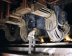
Smelting reduction furnace with connection lines to the electrodes

Electrodes still glowing in the lid swiveled to one side

Low voltage side of the active part of an arc furnace transformer with separately led out ( "nested ") winding beginnings and ends

Arc furnace transformer with open US discharge line for external triangular connection and coplanar, water-cooled pipe penetrations


literature
- G. Volkert, K.-D. Frank: Metallurgy of ferro-alloys . 2nd revised edition. Springer Verlag, Berlin, Heidelberg, New York 1972, ISBN 978-3-642-80580-6 .
- A. Mühlbauer: Industrial electrical heating technology . Vulkan-Verlag, Essen 1992, ISBN 3-8027-2903-X .
Individual evidence
- ^ Post from Dein Chemiepark Knapsack on Facebook , accessed on March 8, 2019
- ↑ Tamini AC or DC Furnace Transformers , accessed March 6, 2019
- ↑ Siemens brochure on industrial transformers , accessed on May 10, 2019
- ↑ a b Transformers Committee of IEEE Power and Energy Society: IEEE Standard Requirements for Arc Furnace Transformers . IEEE-SA Standards Board, New York 2012, p. 9 (7 February 2013).