Electric actuator (control valve)
Electric actuators for control valves, also called control valves , are a variant of the actuators for control valves. A supply of compressed air is not required for this implementation.
Electric actuators
Electric actuators are not only used for control valves , i.e. for control valves . They are generally a type of actuator for fittings such as valves , slide valves and flaps ; Depending on the type of auxiliary energy , a distinction can be made between electrical, pneumatic and hydraulic actuators and combinations thereof. Electric drives can not only be used for movement processes, but also as actuators. These are necessary in a technical system for the automatic regulation and control of the flow of liquids, gases or solids . The electric actuators for fittings use an electric motor and also enable manual operation via a handwheel .
Electric drives for control valves

Continuous electric drives for control valves operate control valves electrically. Within an automation chain, control valves (control valves) have the task of conditioning material flows in such a way that an optimal overall process efficiency is achieved. They can be operated by pneumatic , hydraulic or electric drives . Due to the simpler installation and the smaller device infrastructure required, electric drives are often preferred.
The requirements of the process to be controlled on the actuator are diverse. Different focal points are relevant for the selection. These can e.g. B. be:
- Investment costs for the devices
- Process downtime costs if a component is defective
- Control quality
- Service life
- Maintenance effort
Variable speed drives for low to medium requirements
Drives that operate intermittently are often used for these applications. In the regulated state, the motor is switched off and the actuator is held in the current position either by a brake or the self-locking of the drive and / or gear against the process force. If the process requires a change in the volume or mass flow, the motor starts with maximum torque and moves the actuator. As soon as the deviation between the desired volume or mass flow and the measured volume or mass flow is sufficiently small (the controller is then in the "dead zone"), the motor switches off.
In terms of design, such a drive unit can consist of a modular rotary drive with an additional assembly which converts the multiple rotary movement of the drive into linear or pivoting (partially rotary) movement. Worm gears are often used as gear components, primarily with grease but also with oil lubrication. Compact devices with integrated gears are also possible, in which the direction of movement (linear or pivoting) specified by the actuator is already provided at the output. To protect the actuator and valve, protection or monitoring assemblies such as torque limit switches or thermal switches are usually required. They switch off the motor as soon as an impermissible operating state occurs (e.g. temperature too high; actuator blocked).
Such an arrangement offers a good, reliable and inexpensive solution for the majority of processes and the requirements defined at the beginning. However, it reaches its limits when the process dynamics (frequently and rapidly changing process actual or setpoint value with simultaneously required high control quality) result in a high number of motor switching cycles. This can be up to 1200 c / h and more. High numbers of switching cycles and the resulting peak loads can damage or destroy drive components and thus failure of the actuator. A possible reduction in the number of load cycles by increasing the dead zone of the process controller would, on the other hand, result in losses in process performance.
Continuous control drives for dynamic, high-precision control loops
In order to guarantee a high level of control accuracy with a long service life even for highly dynamic control loops, well-known manufacturers have developed electrical control drives for continuous positioning.
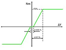
Their main unique selling point is the operating mode. In contrast to the working principles described above, the motor is permanently switched on (duty cycle = 100%). However, this does not necessarily mean that it produces a rotary movement. In the regulated state, it develops just as much torque as is necessary to hold the actuator in position against any pending process force. Driving forces on the one hand and restoring forces from the process then form a sensitive balance. If the process requires a change in the mass or volume flow, the motor increases or reduces its torque gently and proportionally to the increased deviation between the position setpoint and actual value until the desired process variable has been set in the higher-level process control loop.
This behavior, in which no sudden (torque) load peaks occur, makes a significant contribution to protecting the material and thus extending the service life of the variable speed drive. In relation to the entire process, the positioning control loop works as a control loop with P behavior subordinate to the process control loop.
Continuous variable speed drives for swivel movement
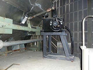
A 3-phase asynchronous motor acts on the actual drive gear via a differential gear . This is usually designed as a spur gear with ball bearings, which runs in an oil bath and thus ensures a high degree of ease of movement. It converts the incoming multiple rotary motion of the motor while increasing the torque into a swivel motion on the output side. A sensor on the back of the drive shaft records the current drive position and transmits this to the control electronics as a current or voltage value.
The exiting shaft end has a working range of up to 120 ° (corresponding to 100%) and can, for. B. when connected to ball valves, directly to the actuator, z. B. can be coupled via a socket-key connection. In flap applications, it is connected to the actuator via a lever and a linkage. This structure enables a position-dependent increase in the torque acting on the flap by choosing the appropriate angle in the linkage connection. In addition, it also causes a thermal decoupling of the drive and actuator.
Due to their design, these drives have extremely low internal friction without any self-locking. The process forces acting on the actuator would therefore move the actuator into an end position if the power supply for the motor fails. To counteract this, the motors are equipped with a brake that works according to the closed- circuit principle . In normal operation, the motor and brake magnet are live. The magnet holds the brake mechanically released against a spring. If the supply voltage fails, the magnet is ineffective and the spring lets the brake engage mechanically. The actuator is held in its current position. Since this process only occurs if the voltage fails or is deliberately switched off, maintenance-relevant frictional wear is negligible.
In addition to the motor, a handwheel also acts on the differential gear on the input side. Once it has been unlocked and the brake applied, the drive can be moved manually if necessary.
Continuous variable speed drives for linear movement
While rotary actuators are mainly used for actuators with partially rotary motion, linear control valves require suitable linear actuators. Since the requirements with regard to responsiveness, service life, ease of movement and robustness in highly dynamic control loops also apply to this type of construction, they correspond in their basic mode of operation and their essential construction elements to the versions for pivoting movement. In contrast to this, however, a linear working movement must now be generated. The 3-phase asynchronous motor therefore acts via the known differential gear on a ball screw drive running in an oil bath . The output gear of this differential gear acts on an axially tied nut, which moves on a spindle which is again radially tied. This generates a linear movement of the threaded spindle when the motor rotates. Its outgoing end is coupled to the valve spindle.
In critical applications, e.g. B. Superheated steam control valves in power plants, there may be a thermally induced change in length of the valve spindle and drive spindle. In order to compensate for this, the entire spindle drive in linear drives from some manufacturers is suspended "floating" in a spring package.
Control electronics
Regardless of the direction of movement of the continuous, electrical control drive, the requirements of continuous rotary or linear drives for the control electronics are identical. On the power side, the electronics work as a frequency converter with pulse width modulation . This allows a wide range in the variance of drive speed and / or drive force / torque without the need for a hardware change (gear ratio).
The power is supplied from the 115V / 230V 1-phase network. A drive-specific software in the electronics monitors and limits the current consumption of the motor if necessary and thus guarantees one of the core functions: the blocking resistance of the drive motor even at max. Torque and speed "0" without time limit. A separate thermal or torque-dependent monitoring and consequently additional components as possible sources of error are not required.
The electronics receive a specification from the higher-level process controller for the currently optimal actuator position (position setpoint); Depending on the technical design, either as an analog value (4… 20 mA) or as a digital value for fieldbus communication. The electronics software constantly compares this with the current actuator position (actual position value). Depending on the result, the drive will now move the actuator to the new position or it will hold it in the current position when the motor is switched on (but not rotating).
Numerous other software functions enable the drive functions to be individually adapted to the process. The scope varies depending on the manufacturer - therefore a general overview below:
- Reduction of moment / force and speed
- Alarm messages
- Error logs
- Signal simulations
- Individual end position behavior
- Behavior in the event of an error
In addition, some manufacturers' devices also offer maintenance management. The parameters relevant to maintenance and service life, such as B. temperature, load peaks, load distribution, number of motor changes in direction of rotation etc. are recorded on the drive and evaluated in an algorithm of the electronics software. The system operator is given the opportunity to plan any maintenance work that may be required depending on the load and avoid unnecessary system downtime due to general maintenance intervals.
A local control panel is usually also part of the electronics. In addition to the option of calling up the basic functions of the drive from there using key commands, it can also include a communication interface with the usual industrial standard. A PC or notebook can be connected here in order to display, read out or change parameters using a graphical user interface.
The electronics can either be part of the variable speed drive (integrated) or they are installed separately. The selection of the type of installation depends on the application. While integrated electronics usually allow a more compact design and a more affordable solution, separate installation offers advantages in terms of accessibility in tight and harsh environmental conditions. Even in the case of thermally critical conditions at the installation location of the actuator, the separate installation has an advantageous effect on the service life of the electronics.
Individual evidence
- ↑ Electric actuators - automation of industrial valves
- ↑ ABB: Technical Description TD / ACTUATOR / 001-DE ( intelligent electrical drives for process automation )
- ↑ ROTORK - Established Leaders in Actuation Valve


