
Short circuit attempt
In electrical engineering, a short-circuit test is a test circuit that is used to check the properties of an electrical machine using measurements. During the short-circuit attempt, the effective resistance is determined by measurement by means of intentional short-circuits .
Circuit design and test execution
transformer
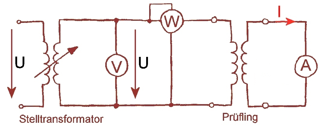
The short-circuit test is particularly necessary for larger transformers , as these cannot be tested under the conditions of rated operation. This is due to the fact that the tests on site due to the changing loads and network conditions do not allow longer-term rated operation. For this reason, transformers are tested in the test field with the short-circuit test. For this purpose, the transformer to be tested is connected to the power grid via a variable transformer . A voltage measuring device is connected to the primary side of the test item for voltage measurement and an amperage measuring device is interposed for current measurement . In addition, a power meter is connected in parallel to the voltage meter. The secondary side of the transformer to be tested is short-circuited. In the case of smaller transformers, the secondary side is short-circuited using an additional ammeter. If the secondary side is short-circuited without an ammeter, only the measured variables on the primary side are measured. The input voltage is then increased starting from zero until the nominal current flows on the primary side . The voltage that is then displayed on the voltmeter is the short circuit voltage . It corresponds exactly to the voltage drop of the transformer during nominal operation. The transformer's copper losses are determined with the power meter . In the event of a short-circuit attempt, the same amount of current heat losses occur on the real transformer as in rated operation. The figure shows a transformer in a short-circuit test. The detailed representation on the left in the figure can be simplified to the representation on the right. The short-circuit current is mainly effective in the longitudinal strand of the transformer, so that the transverse strand is negligible.


Asynchronous motor
The short-circuit test can also be carried out with slip-ring motors . In order to carry out the short-circuit test, the motor shaft must be blocked with a tensioning device and the rotor winding is short-circuited. Since the motor shaft does not rotate, the motor is not cooled by the fan either. To prevent the stator winding from overheating, only a low voltage is applied to the stator winding. The stator voltage is dimensioned so that a maximum of 1.2 times the nominal current flows in the stator . To measure voltage, two voltage measuring devices are connected to the motor connections. An ammeter is interposed in each line to measure the current. The stator current is measured with different voltages and the measured values are entered in a diagram and evaluated accordingly.
literature
- Jens Lassen la Cour: Open-circuit and short-circuit tests in theory and practice. Habilitation thesis, printed by Friedrich Vieweg and son, Braunschweig 1904
Individual evidence
- ↑ a b c Andreas Kremser: Electrical machines and drives, fundamentals, motors and applications. 2nd edition, Teubner Verlag, Stuttgart, 2004, ISBN 3-519-16188-5 .
- ↑ a b E. Arnold (ed.) And Jens Lassen la Cour: The alternating current technology. Second volume; Die Transformatoren, published by Julius Springer, Berlin 1904.
- ↑ a b Detlev Roseburg: Electrical machines and drives. Fachbuchverlag Leipzig in Carl Hanser Verlag, 1999, ISBN 3-446-21004-0 .
- ^ Friedhelm Noack: Introduction to electrical energy technology. Hanser Fachbuchverlag, 2002, ISBN 978-3-446-21527-6 .
- ^ Institute for Electrical Drive Technology and Machines. TU-Graz laboratory exercises on electrical machines and drives, asynchronous machines ( Memento from July 10, 2009 in the Internet Archive )
Web links
- Circuit diagram of a short-circuit test on transformers (accessed on May 5, 2011)