Power meter
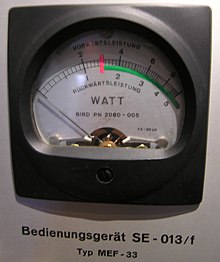
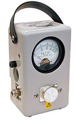
A power meter or power meter is a measuring device that measures power (unit watt ). This can be mechanical power, thermal power, electrical power or radiation power.
Colloquially, electrical power measuring devices, in particular electromechanical measuring mechanisms, are also referred to as wattmeters .
Measure electrical power
Active power measurement
A power meter is not absolutely necessary to determine the electrical power in an electrical circuit . At DC voltage is the electrical power
with - electrical voltage
and - electric current
The power determination with direct current is thus possible by measuring the current strength and voltage.
With alternating voltage, instantaneous values of the power occur corresponding to the instantaneous values of the voltage and the current strength . In reality, the instantaneous values are often not proportional to each other (due to phase shift , distortion of one of the variables), otherwise the measured rms values of current and voltage could also be multiplied for alternating voltage in order to obtain the power. In the general case, a distinction must be made between active power , reactive power and apparent power . The real power is defined by
or
The latter represents an averaging of the instantaneous power over time . In the case of periodic alternating currents with a basic frequency, the integration time must be an integral multiple of the period duration. This option is often used by digital measuring devices. However, it places high demands on devices that can work in a large frequency range and with voltages containing high levels of harmonics or high harmonic currents (high crest factor ). In the case of analog measuring devices, there is usually an integration time due to thermal or mechanical inertia .
In practice, the measurement task can only be satisfactorily solved with the following methods for AC circuits with a low frequency and a not too high proportion of harmonics:
- Electromechanical process with electrodynamic measuring mechanism. It works like a moving coil measuring mechanism , but the moving coil is located in the field of an electromagnet through which the current of the current path flows. The current through the moving coil is supplied with a series resistor in the voltage path; the multiplication results from the Lorentz force ; the averaging results from the mechanical inertia. Such measuring mechanisms can also cope with higher harmonic components and reactive power components.
- Electronically analog process : It works according to the TDM principle (Time Division Modulation). The voltage modulates a pulse width ; the current intensity modulates a pulse height; Demodulation is carried out with a low-pass filter (mean value image), which separates the alternating component with the modulation frequency and the measured variable frequency and delivers a direct signal as a measure for the multiplied variables.
- further electronic procedures:
- Four-quadrant multipliers : There are components ( integrated circuits ) that contain the function of a four-quadrant multiplier; they can be used up into the kHz range. They work on logarithmization, addition and delogarithmization. An averaging device (low pass) must be connected downstream.
- Digital power meter : Instantaneous values of current and voltage are digitized with the highest possible sampling rate with analog-digital converters and calculated in a microprocessor . The devices are often able to obtain other measured values in addition to the active power ( reactive power , crest factor , apparent current , rms values , harmonics ) and also allow three-phase measurements.
For the use of the non-digital power meter for various measurement tasks and the usual circuits, see under active power and reactive power .
Cheap devices for active power measurement and energy metering offered for domestic use often have high measurement errors with a high reactive current component or non-sinusoidal current .
Measurement of high frequency power

In high-frequency technology , the electrical power is measured by measuring the heat of the current in a resistor
determined by measuring the heating associated with the power consumption. The thermal inertia ensures averaging. The ohmic resistance is a terminating resistor that is reflection-free under HF conditions with the size of the wave impedance (typically 50 Ω) with low inductance and capacitance or an impedance-correct line section with a defined resistance of 50 Ω. Non-reflective terminations in waveguides use absorbent wedges.
The temperature increase is measured by temperature sensors along the path to the heat sink or by the temperature-dependent change in resistance of the measuring resistor itself. For this purpose, a small measuring direct current is applied to it. With a defined wave impedance and correct adaptation (no standing waves), the determination of the high-frequency power is also possible via a peak value rectification : Schottky , germanium or gallium arsenide diodes are used. The power here is
With
- - line impedance.
The display must take a correction curve into account due to the forward voltage of the diodes used.
It can level measurement - IC be used for measurements in the dynamic range of z. B. below 1 nanowatt to 25 milliwatt at frequencies up to 1 GHz. The level values are logarithmized and output as a voltage.
Reactive power measurement
Common power meters have a current path and a voltage path . They multiply instantaneous values of voltage and current strength and average the instantaneous values of the product. If real power meters are to be used to determine the displacement reactive power , it must be ensured that current and voltage values are measured with a phase difference of 90 ° from the fundamental frequency. For mechanical devices z. For example, a circuit with inductive or capacitive series resistors can be used in the voltage path instead of the ohmic series resistor, so that the voltage measurement signal is phase-shifted by 90 ° compared to the actual voltage. According to this principle z. B. the bumblebee circuit . The distortion reactive power cannot be recorded in this way.
Digital devices digitize current and voltage (if necessary current and voltage) and calculate the (various) reactive and apparent power (s) from them. With special programs and parameterization, the speed and torque of the connected machine can even be approximated on some devices.
The apparent power can be determined in one phase by multiplying the effective values of current and voltage.
Radiation measuring devices
Power meters for electromagnetic radiation (microwaves, laser radiation, light) work calorimetrically, photometrically or they measure the heat flow, depending on the measuring task.
Calorimetric measurement
The calorimetric measurement requires an absorber that converts the entire output into thermal energy as far as possible. The thermal energy ensures that a body or a quantity of liquid is heated with a temperature gradient that depends on its thermal capacity . The amount of heat is determined either by a defined measuring time and the measurement of the temperature difference before and after the irradiation time, or the temperature gradient is determined itself. The latter method is faster.
Simple devices for determining the laser beam power consist of an absorbent coated metal body with a bimetal thermometer inside . Its pointer shaft passes through a tube to a scale , the zero point of which can be adjusted mechanically. These devices (technical jargon: "bones") are held in the beam for a defined time after the display has been set to zero. After the exposure time, the power value of the scale calibrated in watts is set directly.
Other thermal processes
Another method is also often inappropriately referred to as calorimetric: Here, the temperature difference is measured along a heat conductor that connects the absorber to a heat sink ( heat sink or water cooling). There are temperature sensors on the thermal bridge for this purpose. If you use thermocouples , you get a voltage signal that is directly proportional to the power.
Other thermal methods use pyroelectric sensors and bolometers / microbolometers (bolometer arrays).
Photometric measurement
The photometric measurement is used for near infrared, visible light and low power ultraviolet. For the mid-infrared, cooled photodiodes with a small band gap must be used. The measurements require a photodiode with a known relationship between wavelength, power density and photocurrent as well as mostly a diffuser or an integrating sphere .
While the relationship between photocurrent and power must be calibrated for specific frequencies and devices, the proportionality between photocurrent and power is given over many orders of magnitude. The measurement speed is very high (down to the nanosecond range).
CO 2 laser pulses ( = 10.6 µm) can be measured with photon drag detectors .
Measurement of mechanical performance
See also performance (physics) #Mechanical performance
In translation , force and speed are measured, for example by measuring the power of the draw hook .
During rotation (usually the output power of motors ), calorimetric measurements (braking heat) or by means of an electrical generator coupled to the motor shaft . Furthermore, the can of a shaft power transmitted through the measurement of the rotation - or braking torque and the angular velocity to be determined; see also pendulum machine in engine test benches.
With hydraulics , the pressure difference and volume flow are measured.
Individual evidence
- ↑ LT5537 from Linear Technology
- ↑ http://www.hamamatsu.com/resources/pdf/ssd/b749_kird1038e.pdf photon drag detector in a Hamamatsu company brochure


