Center lathe and spindle lathe
The manually operated master and tension spindle lathe is the basic form of the universal lathe. Almost all turning processes , except for NC form turning, can be used with it. Extensions such as thread cutting attachments or the possibility of turning between points predestine them for use in single or small series production of simple turned parts, but larger quantities are also manufactured on this model in low-wage countries .
Basic ingredients
Headstock

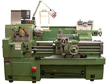
H1 headstock with main gear, H2 speed control for finer gradation of the speeds, H3 speed control with two levels slow / fast, H4 main spindle with mounted three-jaw chuck, H5 controls for direction of rotation and on / off, H6 feed box, H7 lead screw, H8 pull spindle, H9 switch shaft, H10 Removable cover of the belt drive

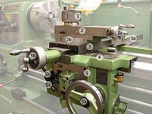
1 quick-change holder, 2 top slides or top support, 2a handwheel for top slide with scale rings, 2b rotatable mounting of the top slide , 3 cross slide, 3a opto-electronic position measuring system of the cross slide, 3b hand wheel for cross slide with scale rings, 4 bed slides, 5 lock case, 5a handwheel for bed slide with scale rings, 5b lever of the lock nut (divisible nut for the feed via the lead screw), 5c lever for inserting the feed
On the left side of the lathe is the headstock with drive, gear and work spindle, at the end of which the clamping tool, usually a lathe chuck , can be attached. A chuck is used to clamp the workpiece or tool. The chuck can be removed so that a three- or four-jaw chuck, a collet chuck, a faceplate or other clamping tool can be used as required.
The hollow construction of the work spindle reduces the centrifugal mass , increases the dimensional stability and, if necessary, longer raw materials up to the size of the work spindle bore can be pushed through. Thus, it is not necessary for these before processing saw off . This can save material and, above all, time.
The work spindle is driven by an electric motor via a belt drive . The speed of older lathes can be varied by moving a belt or by using a gearbox . In modern lathes, motors with stepless speed adjustment are usually installed.
The feed movement is derived from the work spindle to the reversing gear , which switches the feed direction. There is a connection to the feed gear via change gears or toothed belts, with which the feed speed is switched on the guide and pull spindle. Since the feed rate for turning is given in millimeters per revolution, the speed of the work spindle is irrelevant. In newer machines, a ball screw drive replaces the lead screw and draw screw.
Tool slide
On the machine bed, the tool slide (support) can be moved to the left and right by hand with a crank or by automatic feed using a tension or lead screw. The tool slide consists of a bed slide, cross slide, top slide and lock case. The bed slide is the load-bearing unit. The cross slide, which is also connected to the tension spindle via a gear, moves on it. The uppermost unit is the rotatable upper slide with quick-change holder for tool holders, which is arranged parallel to the bed. With the top slide, only manual feed is often possible, with a few, mostly larger center lathes, the feed can also be switched on here. Since the top slide is rotatably mounted, it can be used to turn sharp cones . By switching on a feed and moving the upper slide at the same time, experienced lathe operators can also turn curves.
In order to work economically, a quick-change tool holder with a suitable tool holder is used today to quickly change the lathe tool (see illustration on the right). Occasionally there are still clamps in use in which the turning tool is fixed in a holder with two or three screws. Clamping the turning tools directly on the top slide is no longer permitted today.
If several tools are mounted on the slide in a rotatable device, the " turret head ", the machine is called a turret lathe. The turret tool slide consists of a bed slide, cross slide and turret head. With the turret heads, depending on the position of the axis, a distinction is made between “star turrets” with a vertical axis and “drum turrets” with a horizontal axis.
Tailstock
There is usually a tailstock on the right side of the machine bed. It can be moved to the left or right and clamped at any point. It contains a sleeve that can be moved also by a crank and in a center point or a chuck (for attaching various tools, such as drills , taps be clamped u. Ä.). The center point can be stationary or revolving.
Extensions
Workpiece holder
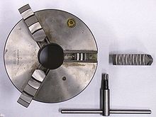
With the lathe chuck , the movements of the individual jaws are coupled via a plane thread in such a way that the components are clamped centrally. The jaws can be used to clamp round workpieces as well as, depending on the number of jaws (three or four), uniformly three, four, six or eight-sided workpieces. Threaded bolts on the chuck connect it to the work spindle by means of a disk ( bayonet disk ). A so-called face plate is used for irregularly shaped workpieces or for eccentric clamping in individual production. Very long workpieces are often turned "between centers", i. This means that the drive plate and drive center are located on the headstock side, and a fixed or moving center on the tailstock side. If the workpiece is to be machined over its entire length, a so-called face driver is used instead of the drive plate that clamps on the circumference . Since in some cases the concentricity of a jaw chuck is insufficient, there are chucks for collets that are more precise.
Automatic feed
In order to be able to remove material evenly, there is an automatic feed. The pull spindle , a shaft with a groove or a hexagonal rod along the machine bed, which rotates in an adjustable ratio to the main spindle, is used for this. A gear in the lock case of the tool slide transfers the rotary movement of the pull spindle to a rack attached to the lathe bed or to the spindle of the cross slide. The slides can be coupled and thus automatically moved proportionally in the longitudinal direction, with better lathes the cross slide mounted on the tool slide.
Thread cutting device
For precise coupling between the rotary movement and the longitudinal feed, lathes often have a lead screw in addition to the pull spindle , mostly for thread turning , the drive components of which are always positively connected to the spindle drive. In other words, gears and, if applicable, toothed belts combine the movements of the rotary drive and longitudinal feed, but not a V-belt. As a rule, the lead screw drive is deliberately only loaded with low forces in order to ensure the accuracy of this drive for a long time. The short formula for this is: tension spindle for force, lead screw for accuracy.
Depending on the equipment of the lathe, internal and external threads in all designs and sizes, such as B. Turn trapezoidal, metric and Whitworth threads , with complex machines with an additional face turning drive also tapered or conical threads. In the case of large internal and external threads as well as rare threads, the appropriate ratio of rotation and feed is set by exchangeable gears in the feed gear or by means of a Norton rocker (a gearbox). In this case, however, the feed movement does not take place via the tension spindle, but via the much more precise lead screw, which is designed as a trapezoidal thread spindle , or in more modern machines as a ball screw drive . With a turning tool shaped to match the thread profile and a feed rate that matches the thread pitch, threads can be turned very easily.
Small internal and external threads are drilled with a cutting device, which disengages or turns from an adjustable torque in order not to damage the drill or the die. In many cases, however, the effort is not worth it. Instead, the machine operator slowly turns the work spindle mechanically or manually and holds the tool firmly by hand.
Steady rest
When machining long workpieces, vibrations can easily occur . These lead to a wavy patterned surface of the workpiece (chatter marks), increased wear and tear on the spindle bearings and noise pollution. In addition, the lathe tool then presses u due to the machining forces. U. the workpiece out of the axis of rotation, whereby the geometry of the workpiece becomes incorrect. It is therefore advisable in these cases to use a center point in the tailstock and press it against the workpiece from the right.
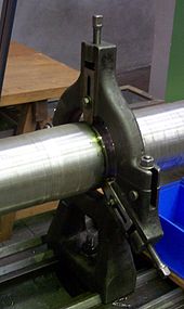
If the use of a center point is not possible or not sufficient due to the desired shape of the workpiece, the use of a steady rest is necessary. The steady rest is placed firmly on the bed between the chuck and the slide. A simple bezel contains three rods made of hardened steel, which can be individually screwed inwards and outwards and pressed radially against the workpiece at intervals of 120 °. With suitable lubrication, this arrangement acts like a slide bearing . Better steady rests have three ball-bearing rollers that turn when pressed against the workpiece.
There are different versions e.g. B. a fixed bezel, as described above, or a rotating bezel. The rotating bezel is attached to the slide and enables z. B. the continuous machining and thread cutting of long shafts or spindles.
Modifications and extensions of the simple lathe
Copy lathe
Copy lathes were manufactured up to the 1970s which, in addition to normal operation, also enable the mapping of a turning contour shape. Here, a clamped flat template with the two-dimensional image of the desired workpiece contour is followed by a hydraulic feeler device; the inward and outward movements of the follower pen are transmitted by a hydraulic system to the face feed in and out, while the longitudinal feed is moved with a fixed value via the tension spindle. Cut by cut, path by path, the infeed depth is now set inwards, the workpiece is machined in several so-called equidistant parallel longitudinal contours until the final contour is reached.
Mechanical automatic lathe, multi-spindle machine
In multi-spindle machines, several simultaneously driven chucks are used in a machine in multiple functions of a single lathe, which are switched with six, eight or more stations in a cycle and work in cycles: the workpieces are loaded and unloaded at one station, and another Rough machining carried out, on further stations partly fine machining, thread cutting or drilling operations.


