
Overhead projector

As an overhead projector or overhead refers optical projector , the transparent films mounted font, images and graphics enlarged to a screen to project. Less common terms are overhead projector , overhead projector or work projector . In the GDR the brand name Polylux was also common as a generic term, in Switzerland overhead projector or Proki writer . This term was also common in the Bundeswehr .
history

The Trajanus von Liesegang projector with the vertical approach from 1927 contains all the elements of a daylight projector. A horizontal work surface is used to project transparencies and flat test arrangements such as magnetic field lines. The projector is in front of the viewer and projects onto a screen behind the speaker.
In 1931, the “Belshazzar” writing and projection apparatus was developed based on a basic idea from Carl Zeiss. A cellophane tape was transported over a 20 × 20 centimeter glass plate on two rollers , which could be written on with a grease pen or special ink. Alternatively, glass or cellophane plates could be written on, slides or objects placed on the projection surface could be used. As with today's versions, the projection was carried out using a mirror with adjustable inclination. A water chamber was used for cooling.
In 1960 the first overhead projector appeared on the market.
functionality


An overhead projector works similarly to a slide projector . The place of the vertical slide is taken by a horizontal, illuminated work surface, usually covered with a writable transparent film. The vertical beam path is continued horizontally to a screen with a mirror arranged after the objective . The work surface for floor-standing devices consists of a pane of glass above the Fresnel lens . The lighting below the Fresnel lens consists of a lamp , an infrared transparent concave mirror and usually a condenser lens , which is often coated to reflect infrared. The lamps used were high-voltage halogen lamps, later low-voltage halogen lamps or metal halide lamps . An economy circuit is often possible to increase the service life of the lamp. The economy circuit only slightly reduces the luminous flux , but increases the service life of the lamp considerably.
The vertical beam path is bundled by the Fresnel lens in the objective and then continued horizontally to a screen via a deflecting mirror.
The redirection on the mirror is made in such a way that the speaker working with the projector has the screen behind him and looks into the audience. He has what is to be projected in front of him, the right way round on the slide, and can add to it by hand during the lecture.
When projecting upwards onto a vertical screen, the image is distorted. A square becomes a trapezoid. To avoid this distortion, the screen can be tilted forward or the lens can be moved. With this lens adjustment , the deflecting mirror also remains lens adjustment at an angle of 45 ° and the projection takes place on the vertical screen, but higher.
When projecting upwards, only by tilting the deflecting mirror accordingly, in addition to the distortion, there is a blurring due to the different distances between the top and bottom of the image. The image is partially out of focus because of the limited depth of field. This blurring can be compensated for by tilting the lens.
The projection is so bright that it usually does not need to be darkened, hence the name “daylight projector”. In the case of compact devices, the lighting device is located on top next to the mirror and the work surface is designed as a mirror Fresnel lens.
Designs
All designs use two standardized sizes for the size of the object field:
- starting from 10 inches, the size is 250 millimeters by 250 millimeters
- Based on DIN A4 portrait / landscape, the size is 285 millimeters by 285 millimeters.
Floor standing devices
The ratio of projection distance to image size can be changed by choosing different lenses. At the same distance, the shorter the focal length, the larger the image and the longer the focal length, the smaller the image. A focal length of 315 mm is usually used for floor-standing devices. A varifocal lens of f = 280-320 mm is often used for compact devices.
| Floor standing units with f = 315 mm | Varifocal lens with f = 280-320mm | ||||||
|---|---|---|---|---|---|---|---|
| Projection distance in m | 1.5 | 2.0 | 2.5 | 3.0 | 1.5 | 1.8 | 2.0 |
| approximate image size in m | 1.2 | 1.6 | 2.1 | 2.5 | 1.3 | 1.6 | 1.8 |
If the device is used in a table or projection cart, all controls on the top of the projector should be accessible. This includes the on-off switch, economy switch, an adjustment option for the lamp housing and possibly also the lamp changer. After opening the worktop, the mains voltage must be forcibly switched off and a defective lamp can then be replaced. To do this, the condenser lens above the lamp has to be opened or removed.
The distance between the work surface and the lens is changed depending on the projection distance when focusing. Since the image of the lamp must be reproduced in the lens, an adjustment is provided for the lighting device. This adjustment is not necessary when using varifocal lenses, as the distance to the worktop is not changed when focusing.
Halogen lamps 24 volts / 250 watts are used as lamps for simple requirements on the luminous flux, and halogen lamps 36 volts / 400 watts for larger requirements. For large rooms with large screen walls, depending on the ambient light 10 square meters and more, versions with metal halide lamps 400 watt or 575 watt are available. Metal halide projectors should have instant reignition.
Travel devices

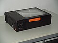
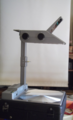
Overhead for transmitted light in projection position
Overhead compact, with folded column for transport
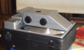
Overhead with symmetrical mirror Fresnel lens in projection position
Overhead compact for transportation


Compact travel devices are either built like floor-standing devices but can be folded up, or they have the lighting system next to the lens in the lens head and the work surface consists of a Fresnel lens that is mirrored on the underside. The lens head can be folded flat on the worktop for transport.
Foldable travel devices can be equipped with brighter lamps, including metal halide lamps, which is not possible for travel devices with mirror fresnel lenses.
For devices that use a mirror Fresnel lens, the projection beam goes through the original twice. First from the lighting system to the mirror Fresnel lens, it is then reflected by the mirror Fresnel lens back to the lens. Therefore, thicker originals, for example motion models or LC support panels, cannot be projected. There are double edges on the projected image. The Fresnel lens is smooth on the top and protected against damage with a protective layer. The grooves are mirrored on the underside. The lens should be as thin as possible to avoid double edges. It is glued to a metal plate for stabilization.
Symmetrical mirror Fresnel lenses cause the lens to be shifted from the center. This creates a small upward projection without distortion. However, the lens must depict a larger image circle.
With asymmetrical mirror Fresnel lenses, the lens can remain in the center above the lens, the requirements for the lens are less high (smaller image circle).
equipment

On the surface of the worktop there are retractable pins for adjusting prefabricated projection films with frames and corresponding holes. On the side surfaces of the housing, there are mounting options for accessories, for example roller devices, vertical or horizontal, or storage areas. An attachment option for a glare shield can be provided on the lens head, which may be necessary for high-performance devices despite the glare-reduced Fresnel lens.
- Roll device: for film rolls five or ten meters, even more
- Storage areas: as storage areas for foils, pens, etc. next to the work surface
- Glare protection: partly required despite glare-reduced Fresnel lenses
- Slide attachment: for the projection of slides in the format 5 cm × 5 cm (for floor-standing devices, until 1998)
- Support panels: for data or video projection (until 1998)
application
Daylight projectors are an alternative to blackboards , whiteboards and flipcharts , also suitable for a larger auditorium . They are used to visualize facts during lectures (for example at school, at universities or during meetings). You can use coherent multi-layer foils (overlays) on one edge, which contain, for example, the lettering of a drawing or various details on foils that can be folded down later. Flat and sometimes even movable models made of transparent plastic that are suitable for laying on (e.g. for math, physics or technical lessons) are available. There are also measuring devices with a transparent display that can be placed on the projector.
In addition, overhead manufacturers themselves have brought support panels onto the market that can replace a video projector . They are placed on the work surface of the overhead projector, and this projects the image displayed on the additional device onto the screen.
Alternatives
Today the overhead projector is being replaced in many places by a combination of video projector and visualizer (document camera ). The image from the camera on the visualizer is transmitted directly to the video projector. This has the advantage that there is no need for transparent projection films. Normal sheets of paper can be used and written on. Alternatively, interactive whiteboards are also used.
A presentation on a computer is also possible on the video projector. Presentation programs enable a design with multimedia content such as animated texts, images and videos. A viewing section of such a program is also called a slide.
Episcopes enable the projection of non-transparent documents such as B. Book Pages. Editing during projection is not possible.
Web links
- An ode to Polylux - on the relevance of overhead projectors and visualizers despite modern presentation programs, archived on November 30, 2012 at http://die-computermaler.de/eine-ode-an-den-polylux/ ( memo from November 30, 2012 on WebCite ).
literature
- DIN 108 part 7 slide projectors and slides; Work projectors; Usable area, retaining pins, projection area, evaluation, date of issue: 1988-12
- DIN 108-7 supplement 1. slide projection; Work projectors, DIN test transparency for minimum requirements with 9 DIN test fields, lines and fonts for practical use, date of issue: 1973-07
- DIN 108-7 Supplement 2. Slide projection and slides; Work projectors, DIN setting transparency for viewing and projection conditions; Date of issue: 1981-12
- DIN 19045-8: 1993-12, projection of still and moving images; Light measurement during image projection with a projector and a separate screen
Individual evidence
- ↑ According to Duden.de, the terms overhead projector and overhead are among the 100,000 most frequent words in the Duden corpus, while overhead projector is beyond the top 100,000 and is rarely or not at all used in the Duden corpus. Google finds more than 6 times as many pages with an overhead projector as with an overhead projector . The terms work projector , daylight writer , Polylux and Prokischreiber are so rare that they are not mentioned in the Duden. The East German name Polylux is listed in the East German sources better evaluating DWDS dictionary as about as often as overhead projector . The Swiss name overhead projector is also in the Duden.
- ↑ Prospectus, Liesegang: Trajanus Epidiaskop . ED.LINTZ AG publishing house, Düsseldorf, 4th edition Nov. 1927, page 7.
- ↑ Wolfgang Grau: Technique of the optical projection . Beuth Verlag GmbH, Berlin 1994, page 380, 423/424, ISBN 3-410-13194-9 and Dipl.-Ing. Mangold, Duisburg: A writing-projection apparatus for lectures , in: Reclams Universum Heft 5, 50th year, Nov. 2, 1933, p. 183 (with ill.).
- ↑ New type of writing and projection apparatus for educational establishments. In: Helios. Trade journal for electrical engineering / Helios. Export magazine for electrical engineering , October 16, 1932, pp. 925-928 (online at ANNO ).
- ^ Projektor , Techniklexikon, accessed online on November 12, 2012
- ↑ Wolfgang Grau: Technique of the optical projection . Beuth Verlag GmbH, Berlin 1994, page 488, ISBN 3-410-13194-9 .
- ^ Gottfried Schröder, H. Naumann: Components of optics , Carl Hanser Verlag, Munich 1992, page 419, ISBN 3-446-17036-7 .
- ↑ Gottfried Schröder, H. Naumann: Components of Optics , Carl Hanser Verlag, Munich, 1992, page 304, ISBN 3-446-17036-7 .
- ↑ Gottfried Schröder, Hanskarl Driver: Technische Optik , Vogel Buchverlag, 2002, page 121 Fig. 6.12, ISBN 3-8023-1923-0 .
- ↑ Gottfried Schröder, H. Naumann: Components of Optics , Carl Hanser Verlag, Munich, 1992, page 304 image 844 b, ISBN 3-446-17036-7 .
- ↑ on different methods of handling overhead projectors and transparencies cf. at Sitte W. 2001