
Slide projector
A slide projector is an opto-mechanical device with which framed slides are projected with light onto a screen, and thus a special projector . It essentially consists of the lighting system with the light source, the imaging system with the lens and the slide holder with the interchangeable system.

Projection lantern with chimney for flame, wooden slider for glass slides, shift lens

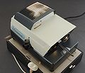
Leitz -Prado slide projector for manual image change, side: operator light
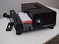
Older slide projector Braun Paximat with cable remote control. Buttons for forward and back
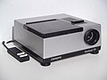
Liesegang Fantimat with universal magazine according to DIN 108 to the right of the beam path


Lighting system

left: concave mirror to increase the amount of light; Lamp;
right: condenser , 2 lenses, heat protection filter in between ; Dia (not shown; its holder is usually just after the right condenser lens)

The lighting system determines the type of use of a slide projector. Criteria are the size of the slides, the required luminous flux and the uniformity of the illumination. On the imaging side, the focal length of the lens determines the size of the projected image and the projection distance to the screen . The beam path of the lighting system and the imaging lens form an interwoven beam path .
The lighting consists of the lamp, the concave mirror behind it and the condenser lenses. The light from the lamp shines through the slide and the luminous element of the lamp is shown in the lens. The lens projects the backlit slide onto the screen.
For smaller slides, an ellipsoid mirror lamp can be used instead of the condenser lens in front of the lamp. Here, too, there is an interwoven beam path and the luminous element of the lamp is shown in the lens.
The light source, the lamp has changed considerably from candles, kerosene light , incandescent lamps , halogen lamps to metal halide lamps . In the course of this series of developments, the achievable luminous flux (measured in lumens), the luminance of the light source and its color temperature increased towards daylight. The increase in the light yield, in the case of electrically generated light the efficiency of the generation of light from consumed electrical power, measured in lumens per watt, reduced the fundamentally undesirable radiation of heat (infrared) from the light source, which heats the slide through absorption. The process-related inevitable absorption of visible light, especially in the dark areas of the slide and the frame, leads to the slide being heated; thermal radiation (high temperature) arriving here is also absorbed and heats up the slide. Simple incandescent lamps only emit around 5% of their electrical power as visible light, 95% as heat. Part of the heat is dissipated via heat conduction (via socket and connecting wires), another part via convection of the ambient air or blown cooling air, the majority of the filament radiates outwards through the lamp bulb according to Stefan-Boltzmann's law .
The energy flow through thermal radiation is even higher with metal halide lamps than that through the proportion of visible light. Slides are made of plastic (or glass) and usually gelatine (the photo layer) and are therefore only temperature-resistant to a limited extent, as are frames made of plastic or cardboard. In glassless slide frames , the film material is not kept flat and, with one-sided exposure, typically bulges in the center of the image in the direction of the lens after a few seconds, since essentially the side facing the lens with the photo layer absorbs light and heat radiation and this side is gradually heated to a higher temperature .
Various strategies serve to reduce the thermal radiation to the slide:
- Heat protection filters in the beam path (after the lamp, just before the condenser) selectively absorb heat radiation (and as little as possible of visible light). Originally a water-filled glass cuvette was used, later a glass filter, typically 5 to 10 mm thick and slightly green in color. Effective heat protection filters heat up strongly according to their high power consumption and are cooled by air convection or blower air.
- Infrared- permeable dichroic mirroring of the collecting mirror behind the lamp, possibly also integrated in the lamp bulb itself, can allow almost half of the relevant heat radiation to escape to the rear.
- Conversely, recently a differently designed dichroic mirroring of the condenser lenses selectively wifts infrared radiation from the beam path of the projection.
- The inside of the optical housing around the light source and beam path is matt and black coated in order to absorb scattered radiation (light and infrared) as well as possible. This wall is mostly made of metal in order to conduct the generated heat to the outside and often has light-tight louvre slots to allow cooling air to penetrate. If housings are made of cast aluminum, they also have a heat-conducting effect via the surface and use the entire surface as a cooling surface. An air space under the housing is also used to improve cooling by means of drafts.
All elements of the beam path, including the slide, are now cooled in parallel by a fan that is as quiet as possible. Blowing hard on the lens is not necessary because it sits on the cold end and because dust deposits are particularly undesirable here.
A small amount of ultraviolet in the light, which would have a particularly strong bleaching effect on color pigments, is readily absorbed by the glass elements (heat protection filter and condenser lenses).
Housings for projectors without fans were built higher to achieve a favorable chimney effect. Projectors with light from flames typically have small chimneys. Its bell-shaped end at the top serves to prevent the undisturbed laminar upflow of the hot exhaust gases with an inflammatory effect .
Projection lens
The projection lens is used for the optical-geometric mapping of the projection template on the screen. It is generally made up of 3 to 5 lenses in order to largely correct imaging errors.
The lenses are designed with a fixed focal length or with an adjustable focal length as a vario lens. Further designs are shift lenses and the CF lens (Curved Field), adapted to the curvature of a slide that is not framed between glass and that has heated up during projection.
When changing the focal length of the lens, the image field lens can be changed or used in a different position in the lamp housing to adapt the interwoven beam paths .
For focusing, the lens must be movable in the optical axis, for example by means of a coaxial thread guide.
The resolution describes the property of lenses to separate closely spaced details. It is generally pictured in line pairs / mm, test sign according to DIN 19051, or by the modulation transfer function , and modulation transfer function (MTF, Eng. Modulation Transfer Function) or modulation transfer function measured.
Projection Distance - Image Size
The relationship between projection distance A and image size B on the screen results from the ratio of the focal length f of the lens to slide width b.
Remarks: It is assumed that the focal length f is much smaller than the projection distance. The nominal size of the slide is specified, for example, for the recording format as 24 mm × 36 mm, but the mask in the slide frame has a size of 23 mm × 35 mm.

| with lens f = 85 mm | ||||
|---|---|---|---|---|
| Projection distance in m | 1.0 | 2.0 | 3.0 | 4.0 |
| approximate image size in m | 0.4 | 0.8 | 1.2 | 1.6 |
| with lens f = 150 mm | ||||
|---|---|---|---|---|
| Projection distance in m | 1.0 | 2.0 | 3.0 | 4.0 |
| approximate image size in m | 0.36 | 0.72 | 1.23 | 1.64 |
Automatic focus
The projected image is usually focused on the screen by turning the lens. This changes the distance between the lens and the slide. This set distance can change due to different slide frames. In addition, the slide is heated in the beam path during projection and bulges, it "jumps". The automatic focus adjustment corrects this change by moving the lens and restores the manually set distance.
Slide change

Zett slide projector with changeable slide

Slides inserted with change slide

Slides inserted through the chute
Slides inserted automatically via long magazine
Slides inserted automatically via round magazine


In the case of projectors with manual slide feed, the framed slides are brought into the projection beam path individually using an interchangeable slide or via a chute.
In the case of projectors with slide feed from a slide magazine , a manual slide change or automatic slide change is possible. The triggering of the forward or reverse (image repetition) can be controlled by different keys or by the pulse length. The automatic slide change can be triggered, depending on the equipment of the projector, by pressing a button on the projector or on the remote control, by a timer or controlled by a tape recorder.
Magazines for slide projectors
Magazines for slide projectors, long magazines or round magazines, are used for slide frames of nominal sizes (3 × 3) cm, (5 × 5) cm, (7 × 7) cm or (8.5 × 8.5) cm. The slide magazines differ in their capacity, i.e. the number of slides and the compartment width for the slide frame. The compartment widths for taking the slides are: up to 1.2 mm or up to 3.2 mm.
Round magazines are particularly suitable for endless presentations. These magazines are also designed for different capacities depending on the manufacturer. In the case of magazines that are arranged horizontally like a carousel above the projector, the slides are guided into the lighting beam path from above; in the case of magazines that are arranged like an upright wheel next to the lighting system, the slides are pushed sideways into the beam path. Round magazines are also intended for slides of nominal sizes 3 × 3 cm and 5 × 5 cm.
Special equipment and accessories
- Timer , adjustable interval for automatic slide change
- With an IR remote control , which usually has to point roughly in the direction of the projector from not too great a distance, the functions of the projector can be controlled remotely.
- Economy switch , reduces the voltage on the lamp by 5%, the luminous flux is reduced by approx. 20%, the service life of the lamp increases by approx. 100%.
- AV control socket, this socket can be used to control the lamp for cross-fades in accordance with the programming of a control device.
- A light pointer can be built into the remote control. The light signal can be used to point out details in the projected image. The V-shaped filament of a special incandescent lamp in a small 3-volt flashlight is sharply depicted on the projection screen by means of a converging lens in the square attachment.
- With the slide preview , a single slide can be viewed before projection, for example on a small screen or a small screen on top of the housing.
- With a photo tape attachment , 35 mm film strips with still images can be projected.
- A microscope approach is used to project transparent microscope slides .
- A tape control uses impulses played on a track of the tape to switch the projector's slide synchronously with the played sound.
- Cross-fading projectors have two lamps next to each other, beam paths and lenses, each of which alternately record a slide, with gentle cross-fading from one image to the next without the dark phase stressing the adaptation of the eye
- A multivision is a projection with two or more projectors, controlled by a multivision control, onto a large screen.
- A projection unit consists of a projector with a transparent screen that is permanently connected to the projector or a fold-out screen.
- One-button operation (for Rollei projectors) works with a short press for an image forwards and sufficiently long press for backwards. Pushing out the previously shown slide is initiated promptly, but the subsequent magazine transport runs one step forwards or backwards, depending on the button position.
- Manual focussing rocker because differently framed or arched or arching slides can make it necessary to readjust the focal plane, the lens can be pushed back and forth using a small eccentric if the eccentric was not at a dead point at the beginning. Also useful in combination with autofocus when different areas are to be focused on a curved slide or only some of the slides are framed in glass, as the autofocus sensor only scans the first reflective surface of the slide from the perspective of the lens.
history
The history of slide projection goes back to the beginnings of the magic lantern , described by Joh. Bapt. Porta back 1589. The first projected templates were shadow projections or drawn templates. Until the 35mm slides were made through photography, initially using coated photo plates , and then 35mm film, and the first 35mm slide projector from Leitz came onto the market in 1926.
literature
- DIN 19021-2, evaluation of standing image projectors with light projection lamps; Temperature measurements on slide projectors; Date of issue: 1985-08
- DIN 19045-8, projection of still and moving images; Light measurements during image projection with a projector and a separate screen; Date of issue: 1993-12
- DIN 19045-9, projection of still and moving images; Light measurements during image projection with projection units; Date of issue: 1993-12
Web links
Individual evidence
- ↑ Helmut Naumann, Gottfried Schröder: Components of Optics. Carl Hanser Verlag, Munich 1992, ISBN 3-446-17036-7 , p. 300.
- ↑ http://www.pradoseum.eu/geschichte.html History of projector production at Leitz / Leica, Pradoseum.at, Web museum about Leitz slide projectors, accessed December 3, 2015.
- ↑ Wolfgang Grau: Technique of the optical projection. Beuth Verlag, Berlin 1994, ISBN 3-410-13194-9 , pp. 148, 159, 420, 500.
- ^ F. Paul Liesegang: The projection system. In: Scientific applications of photography first part. Published by Julius Springer, Vienna 1931, p. 243.
- ↑ Helmut Naumann, Gottfried Schröder: Components of Optics. Carl Hanser Verlag, Munich 1992, ISBN 3-446-17036-7 , p. 301.
- ↑ Philips Lighting Online Academy ( Memento of the original from October 16, 2013 in the Internet Archive ) Info: The archive link was inserted automatically and has not yet been checked. Please check the original and archive link according to the instructions and then remove this notice. (PDF; 1.4 MB) accessed on October 3, 2013.
- ↑ Joh. Bapt. Porta: Magiae naturalis libri viginti Neapoli 1589. Book 17, chap. 1 and 4; in the 1664 edition in Amsterdam p. 574 and 584 In: F. Paul Liesegang: Numbers and Sources, To the history of projection art and cinematography. German Printing and Publishing House, Berlin 1926, p. 7.