Modulation transfer function
The modulation transfer function (also modulation transfer function (MTF ) or contrast transfer function ) is the mathematical description of the comparison between the detail contrast at the edges of an object and the detail contrast of its pictorial representation. There is always a loss of detail contrast. This is not to be confused with the contrast in common parlance, as it can be changed as desired through image processing (or in chemical photography, e.g. through the choice of paper), in particular it can even be increased beyond the original motif contrast.

principle
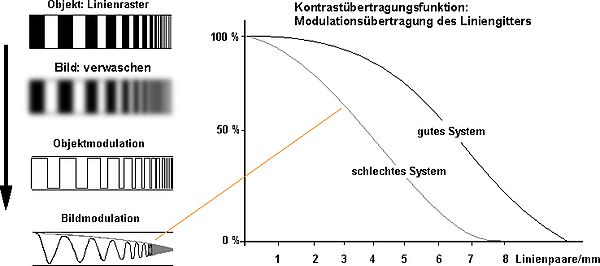
The high-contrast line grid of an object has lost its contrast (washed out) in the visual representation (see graphic on the right). In the mathematical representation, the line grid (of the object) corresponds to an angular curve shape object modulation .
This curve course changes due to the loss of contrast. The new curve progression (of the image with the loss of contrast) is idealized as a sine curve (image modulation).
In this context, modulation means:
- the mathematical representation of a signal (in this case an optical signal).
- the change in the signal (by the imaging system ).
Both modulations (object and image modulation) are compared with one another. The result expresses the amount of contrast loss.
The Heynacher number (based on E. Heynacher from Carl Zeiss ) tries to relate the modulation transfer function to the vision of the human eye. Another psychophysically based variable is SQF ( Subjective Quality Factor ).
Mathematical description
- with f , the spatial frequency of the modulation.
The result is a counting measure with the following properties:
- Advantage: comparability of measurement results
- Disadvantage: The measurement results require idealized conditions .
Specifications

Different object modulations (= curve progressions) can be used to compare the modulations (of the contrast). Typical patterns are the angular curve shape and the sine curve. The selected curve shape is always changed by the imaging systems.
Other measurement variations take other parameters into account.
Applications
In X-ray diagnostics, the MTF for the imaging systems must be checked regularly. The parameters are the limit resolution (spatial frequency at which the modulation drops below 2%) and the characteristic modulation (modulation in percent at the spatial frequency of 1 line pair / mm).
When developing lens systems or optics, the calculation and optimization of the optical transfer function is essential and determines the quality of the device. To simplify this development work, the MÜF is usually no longer calculated experimentally, but using a computer model. Since MÜF is about idealized values, this does not detract from the basic principle of being a comparison value.
Professional cameras have complex lens systems in order to generate as few image errors as possible with high light output, which can be specified with the MÜF. For example, if the lens has a very strong drop towards high frequencies (similar to the pattern in the graphic above), then it does not help to increase the resolution of the detector in order to achieve a better resolution .
When researching the MÜF values on the Internet, we recommend the keyword “data sheet” (as an additional search term).
Hybrid images
In the case of hybrid images, when two similar images are superimposed, an optical illusion is created by manipulating the contrast transfer functions .
swell
- ↑ E. Heynacher: Some remarks on the problem of optical image assessment . In: Journal of Modern Optics, Volume 7, Issue 2 April 1960, pp. 173-178.
- ↑ HH Nasse: How do you read MTF curves? (PDF; 614 kB) In: Carl Zeiss, Photo Lenses Division, December 2008.
-
↑ "The sharpness of the X-ray image is defined subjectively. Since the beginning of clinical radiology, the image of edges has been used time and again to define the sharpness of an image. Due to the different effects of the influences determining the image on the image of an edge, however, no generally satisfactory criteria could be established The reason for this is the fact that the human visual process itself has an influence on the impression of sharpness. Objective criteria that do not fully capture the definition of sharpness, however, are the resolving power of, for example, line grids or, better, the modulation transfer function. "
Radiography Handbook, Dr. Buchmann, 1996 (PDF file; 3.6 MB) - ↑ Contrast Sensitivity Function , Wikibook Digital Imaging Methods , Chapter Basics , accessed on July 5, 2018
- ↑ "... it can happen that with two lenses that have the same MTF data you get completely different images of a detail of the object." (zeiss.com: How do you read MTF curves? )
- ↑ zeiss.com: How do you read MTF curves?
- Theodor Laubenberger: Technology of medical radiology: diagnostics, radiation therapy, radiation protection . 7th edition, Deutscher Ärzteverlag, Cologne 1999, ISBN 3-7691-1132-X
literature
Norms
-
DIN 58185 , optical transfer function
- Part 1: Formula symbols, terms, mathematical relationships
- Part 2: Device basics
- Part 3: Performing the measurement
- Part 4: Representation
- ISO 11421 (1997): Optics and optical instruments - Accuracy of measurements of optical transfer function
- ISO 15529 (2010): Optics and photonics - Optical transfer function - Measurement of the modulation transfer function (MTF) of scanning imaging systems
Web links
- Hubert Nasse: How do you read MTF curves? Part 1 (PDF; 614 kB), Part 2 (PDF; 296 kB), MTF images ( ZIP ; 28.8 MB), Carl Zeiss AG
- Explanation for MTF of films and lenses (English)
- Basics of MTF measurement
- Modulation transfer function
- Markus Bautsch: Modulation Transfer , in: Wikibooks Digital Imaging Methods - Basics


