
Tubular centrifuge
The tube centrifuge separates substances of different densities. It is one of the so-called separators in process engineering . As with all centrifuges , the centrifugal force supports the separation of solid (disperse phase) and liquid components (homogeneous phase), but it is also possible to separate two liquid phases with simultaneous separation of a solid.
In contrast to the laboratory centrifuge, in which the suspension to be separated is filled into centrifuge tubes, the tube centrifuge is a semi-continuous process. Due to the permanent supply and the subsequent harvesting of the centrifuge, significantly higher product quantities can be processed in a short time.
Functional principle of solid-liquid separation (decanting)

The separation process of a tubular centrifuge goes back to the sedimentation tank. In this case, the suspension flows from a higher inlet into the tank. The solids settle on the bottom of the tank and the clarified liquid flows out of the tank from a lower outlet (also called weir).
Physical basics
The flow velocity (v F ) and the sedimentation velocity (v S ) of the respective particle determine where it is deposited in the tank. The flow rate depends on the amount of suspension supplied and the tank geometry. The sedimentation rate is determined by Stokes' equation :


The acceleration due to gravity acting on the particle generates the force that causes the individual particle to sink to the bottom of the tank.
Tube centrifuges work on the same principle, with the acceleration due to gravity being replaced by centrifugal acceleration, which results in a significantly higher sedimentation speed of the particles.
With the centrifugal acceleration acting in the centrifuge:

For the Stokes equation we get :


- Formula symbols used and their meaning
| character | meaning |
|---|---|
| Centrifugal acceleration | |
| Speed in min −1 | |
| Mass of the particle | |
| Radius from the center of the rotor to the particle | |
| Sedimentation rate | |
| Acceleration due to gravity | |
| Radius of the particle | |
| Density of the particle | |
| Density of the liquid | |
| Dynamic viscosity of the liquid | |
| R elative C entrifugal F orce (relative centrifugal force), also called spin index |


Basic structure
Two key findings follow from this:
- The force on the particle, and thus its sinking speed, increases quadratically with the speed of the centrifuge.
- As particles get smaller (e.g. nanoparticles ), the rate of descent is reduced by the square of the size of the particle.
The essential design feature of this type of centrifuge results from the requirement of the highest possible centrifugal forces: a tubular solid bowl rotor. The solids collect in this rotor during the centrifugation process. In practice, it has proven useful to specify the centrifugal acceleration as a multiple of the acceleration due to gravity , according to the following equation:

Modern tube centrifuges achieve a relative centrifugal force of 80,000, more than 100,000 have already been achieved in research projects. In such centrifuges, very high quality steels are used to absorb the material stresses that occur, mainly in the form of tangential stress.
Procedure
The centrifuge starts in a dry state. When the final speed is reached, the suspension begins to be injected into the rotor, shown in light green in the picture. The solids are then deposited on the rotor wall (dark green). The clarified liquid, the centrate , leaves the rotor via the weir and is collected in the so-called collecting bowl. A suitable line guides the clarified liquid out of the centrifuge housing.

Depending on the suspension used, either the clarified liquid or the solid remaining in the rotor is the desired product. To remove the solid matter from the rotor, the centrifuge must be shut down in order to remove the rotor, inside of which the solid matter has been deposited.
advantages
Of all centrifuges based on the continuous flow principle (the suspension is fed in continuously), tube centrifuges generate the highest forces within the rotor. This makes it possible to separate even very small particles (diameter ~ 10 nm). Such particles are usually present in very low concentrations, which benefits the tubular centrifuge in terms of its properties. In general, this type of centrifuge is particularly suitable when the proportion of solid matter within the suspension is in a range below 10%. This technology has great advantages, especially with very low solids content (<1%).
When removed, the solid usually has a vaseline-like consistency and is easy to remove. In rare cases, the high force on the particles also creates stronger structures (e.g. titanium dioxide).
In contrast to corresponding filter methods, the lack of a filter means that there is no loss of product in the filter materials used when using the tubular centrifuge. The solids obtained with the centrifuge often have a very high material value. Losses that get stuck in filter materials are therefore undesirable.
disadvantage
The high speeds of the tube centrifuge require a precise coupling of rotor and drive. To remove the solid, this connection must be loosened and the rotor removed from the centrifuge housing. Although this is possible in a simple manner due to the design, it has so far been an essential manual work step.
In the meantime, centrifuges are also on the market that circumvent this fact by automatically discharging the solids, but these currently only achieve a fraction of the spin rate.
Areas of application
Separation of bacteria and viruses
With the emergence of gene-adapted bacteria , primarily Escherichia coli , or yeasts , for the production of certain enzymes as the basis of drugs, further areas of application were added. Today tube centrifuges are used behind many fermenters to separate the bacteria from the nutrient liquid in the first step of downstream processing .
Separation of nanoparticles
The emergence of nanoparticle production in chemical reactors has also expanded the field of application of this type of centrifuge. After being generated in the reactor, nanoparticles are usually present in very low volume concentrations. Tube centrifuges are particularly suitable here for the gentle separation of the desired particles. This process is also known as downstream processing . Since 2015, the European Union has supported research projects such as the Co-Pilot project as part of the H2020 call. Initial research results show that the tubular centrifuge is very well suited to separating the nanoparticles in such a way that excellent redispersion is achieved, for example in plastics.
Functional principle of liquid-liquid separation
Analogous to the sedimentation tank for solid-liquid separation, the communicating tubes show the functional basis for separating two mixed liquids of different densities. In most cases, one liquid is emulsified as small droplets within the other . First, centrifugal force separates the two phases from each other, analogous to the solid-liquid separation. A corresponding arrangement of the weirs ensures, as described below, that the liquids are discharged separately from the centrifuge.
Physical basics

Due to the lower density of the light phase (e.g. oil), its level is higher than that of the heavy phase (e.g. water)!
At the imaginary interface, the pressure of the two liquid columns is the same, with: at the interface:


- Formula symbols used and their meaning
| character | meaning |
|---|---|
| Heavy phase density | |
| Density of the light phase | |
| Height of the separation point | |
| Level of the easy phase | |
| Difficult phase level | |
| Acceleration due to gravity | |
| Centrifugal acceleration | |
| Inner weir radius | |
| Outer weir radius | |
| Radius separation point | |
| Inner radius of the rotor |


Basic structure
This effect of the layered liquids is used when separating two liquid media in the centrifuge. The hydrostatic paradox shows that the shape of the vessel on both sides of the imaginary separation point is irrelevant for the function.
The mechanical structure of the centrifuge means, mostly through corresponding channels in the head of the rotor, that in this case there are two weirs. The centrifugal acceleration ensures the separation of the mixture of substances. As a result, the heavy phase is deposited near the rotor wall, the light phase is layered over it. Analogous to the communicating tubes one would assume:

by
there is a clear dependence of the centrifugal acceleration on the radius. In order to get the real pressure at the separation point, it is necessary to integrate over the radius. One thus obtains:


The light phase emerges from the inner weir, the heavy phase from the outer one. Two separate collecting trays collect the droplets thrown off by the rotor and guide them out of the centrifuge.
The inner weir is often technically formed by a separating ring, which should be exchangeable. Due to the inner diameter of this separating ring, expressed by in the above formula , the centrifuge can be adjusted to almost any density ratio of the two liquid phases.
Inherent special case of three-phase separation
Many users wonder about deposits in the cylinder when using the tube centrifuge. Due to the design, the tubular centrifuge is always a so-called three-phase separator. All fine particles that are still contained in the two liquid phases are also subject to centrifugal acceleration. Due to the high speed of the tubular centrifuge, fine particles are also separated from the two liquid phases in parallel to the liquid-liquid separation process.
Procedure
The operation of the machine is identical to the solid-liquid separation, apart from a few details. The separate collecting trays ensure that the two liquids leave the housing of the centrifuge on separate paths. In this process step, it is important to fill the centrifuge. It is of great importance that when you inject the liquid you start by feeding in a clean heavy phase. This must first fill the point that relates to the hydraulic balance. If this rule is not adhered to, it can happen that at the beginning of the separation process, light phase still emerges on the drain of the heavy phase. After the heavy phase then emerges at the corresponding lower outlet, the substance mixture is activated, usually via appropriate valves.
advantages
Compared to separators, which are most frequently used to separate two liquids, the rotating movement of the rotor only causes very little turbulence between the two liquids. This makes the separation process easier. The rotating disks of separators create turbulence between the liquids. This can cause parts of the light phase to escape from the heavy phase and vice versa.
disadvantage
The disadvantages of manual coupling and clearing of the rotor shown in the case of solid-liquid separation are only given to a limited extent in liquid-liquid separation. The actual liquid-liquid separation takes place continuously. Even in small rotors with a nominal capacity of only 2 liters, several hundred or even thousands of liters of liquid can easily be separated. Since in the majority of cases only very small proportions of solid matter get into the centrifuge, the rotor very rarely has to be shut down and the remaining solid matter removed.
Areas of application
Blood fractionation
The classic place of application of the tubular centrifuge was originally the fractionation of blood (even a suspension) on a large scale. As early as the 1920s, the inventor of the tube centrifuge, the Sharpless company (no longer in existence today, the brand name was sold), used these centrifuges for mass fractionation of blood. To this day, this type of centrifuge is used to extract raw materials from the blood (both human and animal) for the manufacture of medicines.
Extraction of vegetable oils
When grinding or pressing vegetable oils, in addition to the oil you are looking for, vegetable sap and fiber residues are also pressed out. The separation of the oil from the aqueous plant sap phase and the coarse dirt is often carried out in separators . Tube centrifuges are used for the subsequent fine cleaning of the oil.
history

The tubular centrifuge was developed in the so-called "open" design (from Sharpless). This version is still available today, housed in a gray cast iron housing. The term "open" results from the basic idea that the thrown off aerosols are caught in the bowls, but can escape from the "open" housing in many places. This has repeatedly led to criticism from many users, especially with odor-intensive products. The disruptive, gaseous odorous substances use the gaps between the rotor and the collecting trays. The closed design was only developed later. At first also exclusively as gray cast iron, now also in stainless steel. The entire process is sealed in the closed housing in such a way that as few aerosols as possible can leave the housing. At the beginning this version was still equipped with a compressed air turbine.
Current designs
The two historically developed models have been preserved in their basic function to this day. The development, together with the update of DIN EN 12547 "Centrifuges - General Safety Requirements", has led to the current state of the art. Modern safety controls control the safety devices such as door locking, safe stopping, etc.
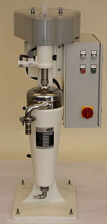
Tube centrifuge Z61, current design. Rotor content 6 liters.
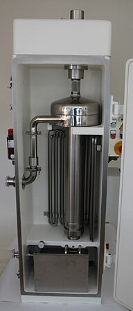
Tube centrifuge Z61G, rotor capacity 6 liters.
Tube centrifuge Z11, max. Spin number = 80,000 g


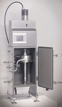
Tube centrifuges with CIP facilities

Its use in the biochemical and pharmaceutical industries has primarily driven the Cleaning in Place (CIP) area. Cleaning liquid is fed into the interior of the centrifuge by means of spray nozzles in order to achieve fully automatic cleaning of the interior. The rotor can still be removed manually in most models.
Particularly high speeds can be achieved with direct drives from the motor spindle area. It is currently possible to achieve spin figures of up to 80,000 * g. Due to the high tangential stresses that occur, this version is currently still limited to very small rotor types (0.25 l solid content).
Individual evidence
- ↑ Klaus Luckert: Handbook of mechanical solid-liquid separation , Vulkan, 2004, ISBN 978-3802721960
- ↑ a b c Werner H. Stahl: Industrial Centrifuges: Operating Technology & Process Integration , DRM Press, 2008, ISBN 978-3952279427
- ↑ H2020 https://ec.europa.eu/programmes/horizon2020/h2020-sections
- ↑ Project Co-Pilot: http://www.h2020copilot.eu/
- ↑ Publication: Continuous flow synthesis and cleaning of nano layered double hydroxides and the potential of the route to adjust round or platelet nanoparticle morphology http://pubs.rsc.org/en/content/articlelanding/2016/ra/c6ra09553d#!divAbstract
- ^ Lew Dawidowitsch Landau , Jewgeni Michailowitsch Lifschitz : Statistical Physics. Part I. Akademie Verlag , Berlin 1979/1987, ISBN 3-05-500069-2 , p. 70.