
SAR class 1E
| SAR class 1E | |
|---|---|
 |
|
| Numbering: | E1-E190 |
| Number: | 172 |
| Manufacturer: | SLM , Metrovick , Werkspoor , RSH |
| Year of construction (s): | 1923-1944 |
| Retirement: | until 1990 |
| Axis formula : | Bo' – Bo ' |
| Gauge : | 1067 mm ( cape track ) |
| Length over coupling: | 13,310 mm |
| Height: | 3,962 mm |
| Width: | 2,800 mm |
| Bogie axle base: | 2,819 mm |
| Total wheelbase: | 9,423 mm |
| Smallest bef. Radius: | 90 m |
| Service mass: | 69 t |
| Wheel set mass : | 17.3 t |
| Top speed: | 72 km / h |
| Hourly output : | 4 × 224 kW = 896 kW |
| Starting tractive effort: | 176 kN |
| Hourly traction: | 95 kN |
| Continuous tensile force: | 73 kN |
| Driving wheel diameter: | 1219 mm |
| Power system : | 3 kV direct current |
| Number of traction motors: | 4th |
| Drive: | Paw camp |
| Brake: | Westinghouse air brake; Drag brake ; Regenerative brake |
The class 1E of the South African Railways is an electric locomotive for use with 3 kV DC . The series, put into service between 1925 and 1945, comprised 172 locomotives, which were delivered in seven sub-series. The series developed by Metropolitan-Vickers ( United Kingdom ) and SLM ( Switzerland ) was the first electric mainline locomotive to be used in South Africa . 35 units of this series were converted to class 1ES shunting locomotives .
history
At the beginning of the 1920s, the 275 km Glencoe - Pietermaritzburg stretch reached the limit of its capabilities. The mountain railway is part of the Johannesburg - Durban line , which is mainly used to transport coal from inland to the coal terminal in the port of Durban. The route has steep gradients and tight curves. The apex is at Nottingham Road at 1,464 m above sea level. At that time there were two routes between Glencoe and Pietermaritzburg, a newer one with a 15 ‰ gradient and an older one with a 30 ‰ gradient. The routes were designed for trains with an axle load of 18 t.
The South African Union decided to electrify the line in order to increase its efficiency. An important argument for the project was the saving in personnel costs. The electrification was to reduce the workforce from 300 drivers and stokers to 170 drivers and men . In addition, electrification should increase the average speed of trains. Instead of the 13 km / h of steam operation, 34 km / h should be achieved with the electric locomotives. The total capacity of the route should increase by 60%.
The electrification project was developed by the English engineering firm Merz & McLellan. The line was to be electrified with 3000 V direct current so that locomotives could be built with two 1500 V traction motors connected in series.
English firms received a contract worth four million pounds sterling . Metropolitan Vickers received the order to build the four-axle locomotives with pawl bearing drives . The order for the mechanical part was subcontracted by Metrovick to SLM in Switzerland.
The intended class 1E locomotives were the first electric locomotives in South Africa. They were supposed to transport a train of 1620 t in triple traction on a gradient of 10 ‰ at a speed of 35 km / h. You should also be able to pull up the same train on the incline and reach the required speed after three minutes. In a 20 ‰ gradient, the three locomotives should be able to keep a train of 1475 t at constant speed with the electric brake. The maximum speed of the locomotives should be 72 km / h. In the horizontal plane, the locomotives should reach 58 km / h with the same train.
For the electrification of the Glencoe – Pietermaritzburg section, the newer route with the 15 ‰ gradient was selected. Construction work was already underway in 1923.
Electrical operations began in 1925 between Glencoe and Pietermaritzburg and expanded to Durban in 1936. On this occasion, the line between Cato Ridge and Durban was expanded to double track. In addition to the construction of longer cuts and dams, the difficult terrain also required the construction of ten tunnels.
The traction power supply was ensured by the Colenso power station, which was approximately halfway between Glencoe and Pietermaritzburg. The 50 Hz electricity generated in the power plant was conducted with a voltage of 88 kV to the substations , where it was transformed to 6.6 kV and converted into 3 kV direct current by a converter . Each set of converters had a continuous output of 2 MW and could deliver 6 MW for five minutes. Two 1500 V direct current generators connected in series and driven by a synchronous motor arranged in the middle sat on the shaft . For the operation of the Glencoe – Pietermaritzburg line, 21 converter sets were required, which were arranged in 12 substations. The converter sets were designed for automatic operation, which made the system supplied by British Thomson-Houston the largest traction power supply with automatically operated substations when it went into operation.
Manufacturer


The order for the first 78 class 1E locomotives was the largest order ever placed worldwide for electric locomotives of a single series. The electrical part was designed by Metropolitan-Vickers, the mechanical part by SLM. The locomotive was built in seven series by four manufacturers between 1925 and 1945 and delivered to the South African Railways. The whole series comprised 178 locomotives. While the mechanical part came from different manufacturers, the electrical equipment was always supplied by Metropolitan Vickers.
The first locomotives only had English license plates. Afrikaans became the second official language in South Africa in 1938, so that from the 5th series onwards, the locomotives received bilingual license plates.
The 1st series comprised 60 locomotives E1 to E60, the mechanical parts of which were built by SLM in Winterthur from 1923 to 1924 , and the 18 locomotives E61 to E78, the mechanical parts of which were built by Metrovick itself in 1925.
The 2nd series consisted of 17 locomotives with the numbers E79 to E95, which were built by Metrovick between 1925 and 1926.
The 3rd series consisted of 5 locomotives with the numbers E98 to E102, which were built by Metrovick in 1936. The omitted numbers E96 and E97 went to the first two class ES locomotives.
The 4th series consisted of 20 locomotives with the numbers E103 to E122, which Metrovick also built in 1936.
The 5th series comprised 25 locomotives with the numbers E139 to E160, which were built by SLM in 1938. The omitted numbers E123 to E138 went to locomotives of classes ES1 , ES , 2E , DS and DS1 .
The 6th series comprised 20 locomotives with the numbers E161 and E180, which were built by the Dutch Werkspoor in 1938 .
The 7th series comprised 10 locomotives with the numbers E181 to E190, which were built by RSH in 1944.
technology
Mechanical construction
The class 1E locomotives had a locomotive body without a front end that rested on two bogies with two axles. The coupling was attached to the bogies, which were connected to each other with tie rods, so that no tensile forces were transmitted via the locomotive body. This construction method was also used for the following classes 2E , 3E and 4E .
The boxes with the batteries for the control power supply were arranged under the locomotive box.
The locomotives had a driver's cab at each end, and both side walls had four windows. In the left side wall there was a ventilation grille under each window, in the right only under the two middle windows. (The designations on the left and right are seen from the driver's point of view when he looks at the route in driver's cab 1.)
The roof over the engine room could be partially removed so that heavy electrical equipment could be removed from the top of the locomotive body for repair and maintenance purposes.
Main circuit
The overhead contact line voltage from the overhead line was fed to the locomotive via two pantographs. Two traction motors were always connected in series. The voltage on the traction motors was regulated by series resistors, which could be short-circuited in stages via a cam switch . When starting up, all drive motors were connected in series; at higher driving speeds, both motor groups were connected in parallel. The regrouping took place via electropneumatic contactors, which were also used to reverse the direction of travel and to weaken the field. The locomotive could thus run four different speed levels economically without converting energy in the series resistors into heat.
Engine room
The two driver's cabs were connected by a corridor along one side wall of the engine room. In the middle of the machine room was the high-voltage chamber with the high-speed switch , the series resistors, the electro-pneumatic contactors and the cam switches.
A compartment for the rest of the equipment was arranged behind each driver's cab. This comprised the auxiliary operations, which consisted of two converter sets with a flange-mounted drive motor fan, a compressor and a vacuum pump. One of the converter sets had an output of 16 kW, the other one of 28 kW. The field of the larger converter replacement could be regulated by contactors. The air tanks for the brakes and the low-voltage devices for controlling the locomotive were also housed in the equipment rooms.
Regenerative brake
The locomotives of the later series received not only the resistance brake but also a more powerful regenerative brake , which allowed higher speeds on slopes. It made the cable routing less dependent on the air brake and had the additional benefit of saving electrical energy. It was one of the first major applications of regenerative braking in normal operation in locomotives with multiple controls. The first series, which were only supplied with a resistance brake, received the regenerative brake installed later.
commitment
The locomotives were mainly used in Natal , but were also used in the industrial regions on the Witwatersrand in the Transvaal (today mainly Gauteng ) or in the Western Cape region . Some locomotives had a mileage of more than eight million kilometers before they were taken out of service.
Conversions
The class 1E locomotives were used in front of both freight and passenger trains. Their maximum speed of 72 km / h was considered too low for passenger train service, so that in 1936 two, according to other sources, three locomotives were given a different translation for use in front of passenger trains. The converted locomotives reached 90 km / h.
Class 1ES
Around 1934, two 1E electric shunting locomotives with a central driver's cab were installed on the bogies and other still usable parts. The design came from the then Chief Mechanical Engineers AG Watson, the renovation took place in Pietermaritzburg. The locomotives used in Daimana, today Danskraal, were designated as 1ES and had the numbers E96 and E97, with the S standing for shunting (German: " shunting "). The locomotives were later renumbered E500 and E501.
The locomotives were successful, so that more class 1ES locomotives were built. A total of 35 class 1E locomotives were withdrawn from line service and converted into shunting locomotives. During the renovation, they received modified starting resistances adapted to the shunting service and larger driver's cabs, but the gearboxes were taken over from the mainline locomotives. Apart from the larger cab, the locomotives were externally recognizable by the front windows, which had a sloping upper edge. The class 1E windshields were rectangular and thus had an upper edge that ran parallel to the lower edge.
In 1964, two of the above-mentioned Class 1ES locomotives were converted to class ES locomotives.
Retirement
All class 1E and 1ES locomotives were retired by 1990.
Factory numbers
The individual class 1E locomotives are listed in the following table with manufacturer, serial number and year of construction. The conversions to locomotives of classes ES and 1ES are listed in a separate column.
| class | series | Locomotive no. | builder | Serial number | year | modification |
|---|---|---|---|---|---|---|
| 1E | 1 | E1 | SLM | 2875 | 1923 | |
| 1E | 1 | E2 | SLM | 2876 | 1923 | |
| 1E | 1 | E3 | SLM | 2877 | 1923 | |
| 1E | 1 | E4 | SLM | 2878 | 1923 | |
| 1E | 1 | E5 | SLM | 2879 | 1923 | |
| 1E | 1 | E6 | SLM | 2880 | 1923 | |
| 1E | 1 | E7 | SLM | 2881 | 1923 | |
| 1E | 1 | E8 | SLM | 2882 | 1923 | |
| 1E | 1 | E9 | SLM | 2883 | 1923 | |
| 1E | 1 | E10 | SLM | 2884 | 1923 | |
| 1E | 1 | E11 | SLM | 2885 | 1923 | |
| 1E | 1 | E12 | SLM | 2886 | 1923 | |
| 1E | 1 | E13 | SLM | 2887 | 1923 | |
| 1E | 1 | E14 | SLM | 2888 | 1923 | |
| 1E | 1 | E15 | SLM | 2889 | 1923 | |
| 1E | 1 | E16 | SLM | 2890 | 1923 | |
| 1E | 1 | E17 | SLM | 2891 | 1923 | |
| 1E | 1 | E18 | SLM | 2892 | 1923 | |
| 1E | 1 | E19 | SLM | 2893 | 1923 | |
| 1E | 1 | E20 | SLM | 2894 | 1923 | |
| 1E | 1 | E21 | SLM | 2895 | 1923 | |
| 1E | 1 | E22 | SLM | 2896 | 1923 | |
| 1E | 1 | E23 | SLM | 2897 | 1923 | |
| 1E | 1 | E24 | SLM | 2898 | 1923 | |
| 1E | 1 | E25 | SLM | 2899 | 1923 | |
| 1E | 1 | E26 | SLM | 2900 | 1923 | |
| 1E | 1 | E27 | SLM | 2901 | 1923 | |
| 1E | 1 | E28 | SLM | 2902 | 1923 | |
| 1E | 1 | E29 | SLM | 2903 | 1923 | |
| 1E | 1 | E30 | SLM | 2904 | 1923 | |
| 1E | 1 | E31 | SLM | 2905 | 1923 | |
| 1E | 1 | E32 | SLM | 2906 | 1923 | |
| 1E | 1 | E33 | SLM | 2907 | 1923 | |
| 1E | 1 | E34 | SLM | 2908 | 1923 | |
| 1E | 1 | E35 | SLM | 2909 | 1923 | |
| 1E | 1 | E36 | SLM | 2910 | 1923 | |
| 1E | 1 | E37 | SLM | 2911 | 1923 | |
| 1E | 1 | E38 | SLM | 2912 | 1923 | |
| 1E | 1 | E39 | SLM | 2913 | 1923 | |
| 1E | 1 | E40 | SLM | 2914 | 1923 | |
| 1E | 1 | E41 | SLM | 2915 | 1923 | |
| 1E | 1 | E42 | SLM | 2916 | 1923 | |
| 1E | 1 | E43 | SLM | 2917 | 1923 | |
| 1E | 1 | E44 | SLM | 2918 | 1923 | |
| 1E | 1 | E45 | SLM | 2919 | 1923 | |
| 1E | 1 | E46 | SLM | 2920 | 1923 | |
| 1E | 1 | E47 | SLM | 2921 | 1923 | |
| 1E | 1 | E48 | SLM | 2922 | 1923 | |
| 1E | 1 | E49 | SLM | 2923 | 1923 | |
| 1E | 1 | E50 | SLM | 2924 | 1923 | |
| 1E | 1 | E51 | SLM | 2925 | 1923 | |
| 1E | 1 | E52 | SLM | 2926 | 1923 | |
| 1E | 1 | E53 | SLM | 2927 | 1923 | |
| 1E | 1 | E54 | SLM | 2928 | 1923 | |
| 1E | 1 | E55 | SLM | 2929 | 1923 | |
| 1E | 1 | E56 | SLM | 2930 | 1923 | |
| 1E | 1 | E57 | SLM | 2931 | 1923 | |
| 1E | 1 | E58 | SLM | 2932 | 1923 | |
| 1E | 1 | E59 | SLM | 2933 | 1923 | |
| 1E | 1 | E60 | SLM | 2934 | 1923 | |
| 1E | 1 | E61 | Metrovick | 1925 | ||
| 1E | 1 | E62 | Metrovick | 1925 | ||
| 1E | 1 | E63 | Metrovick | 1925 | ||
| 1E | 1 | E64 | Metrovick | 1925 | ||
| 1E | 1 | E65 | Metrovick | 1925 | ||
| 1E | 1 | E66 | Metrovick | 1925 | ||
| 1E | 1 | E67 | Metrovick | 1925 | ||
| 1E | 1 | E68 | Metrovick | 1925 | ||
| 1E | 1 | E69 | Metrovick | 1925 | ||
| 1E | 1 | E70 | Metrovick | 1925 | ||
| 1E | 1 | E71 | Metrovick | 1925 | ||
| 1E | 1 | E72 | Metrovick | 1925 | ||
| 1E | 1 | E73 | Metrovick | 1925 | ||
| 1E | 1 | E74 | Metrovick | 1925 | ||
| 1E | 1 | E75 | Metrovick | 1925 | ||
| 1E | 1 | E76 | Metrovick | 1925 | ||
| 1E | 1 | E77 | Metrovick | 1925 | ||
| 1E | 1 | E78 | Metrovick | 1925 | ||
| 1E | 2 | E79 | Metrovick | 1925-26 | ||
| 1E | 2 | E80 | Metrovick | 1925-26 | ||
| 1E | 2 | E81 | Metrovick | 1925-26 | ||
| 1E | 2 | E82 | Metrovick | 1925-26 | ||
| 1E | 2 | E83 | Metrovick | 1925-26 | ||
| 1E | 2 | E84 | Metrovick | 1925-26 | ||
| 1E | 2 | E85 | Metrovick | 1925-26 | ||
| 1E | 2 | E86 | Metrovick | 1925-26 | ||
| 1E | 2 | E87 | Metrovick | 1925-26 | ||
| 1E | 2 | E88 | Metrovick | 1925-26 | ||
| 1E | 2 | E89 | Metrovick | 1925-26 | ||
| 1E | 2 | E90 | Metrovick | 1925-26 | ||
| 1E | 2 | E91 | Metrovick | 1925-26 | ||
| 1E | 2 | E92 | Metrovick | 1925-26 | ||
| 1E | 2 | E93 | Metrovick | 1925-26 | ||
| 1E | 2 | E94 | Metrovick | 1925-26 | ||
| 1E | 2 | E95 | Metrovick | 1925-26 | ||
| 1E | 3 | E98 | Metrovick | 1936 | ||
| 1E | 3 | E99 | Metrovick | 1936 | ||
| 1E | 3 | E100 | Metrovick | 1936 | ||
| 1ES | 3 | E101 | Metrovick | 1936 | Conversion to 1ES | |
| 1E | 3 | E102 | Metrovick | 1936 | ||
| 1E | 4th | E103 | Metrovick | 1936 | ||
| 1ES | 4th | E104 | Metrovick | 1936 | Conversion to 1ES | |
| 1ES | 4th | E105 | Metrovick | 1936 | Conversion to 1ES | |
| 1ES | 4th | E106 | Metrovick | 1936 | Conversion to 1ES | |
| 1ES | 4th | E107 | Metrovick | 1936 | Conversion to 1ES | |
| 1ES | 4th | E108 | Metrovick | 1936 | Conversion to 1ES | |
| 1ES | 4th | E109 | Metrovick | 1936 | Conversion to 1ES | |
| 1ES | 4th | E110 | Metrovick | 1936 | Conversion to 1ES | |
| 1ES | 4th | E111 | Metrovick | 1936 | Conversion to 1ES | |
| 1ES | 4th | E112 | Metrovick | 1936 | Conversion to 1ES | |
| 1ES | 4th | E113 | Metrovick | 1936 | Conversion to 1ES | |
| 1ES | 4th | E114 | Metrovick | 1936 | Conversion to ES E525 | |
| 1ES | 4th | E115 | Metrovick | 1936 | Conversion to 1ES | |
| 1ES | 4th | E116 | Metrovick | 1936 | Conversion to 1ES | |
| 1ES | 4th | E117 | Metrovick | 1936 | Conversion to 1ES | |
| 1ES | 4th | E118 | Metrovick | 1936 | Conversion to 1ES | |
| 1ES | 4th | E119 | Metrovick | 1936 | Conversion to 1ES | |
| 1ES | 4th | E120 | Metrovick | 1936 | Conversion to 1ES | |
| 1ES | 4th | E121 | Metrovick | 1936 | Conversion to 1ES | |
| 1ES | 4th | E122 | Metrovick | 1936 | Conversion to 1ES | |
| 1ES | 5 | E139 | SLM | 3655 | 1938 | Conversion to 1ES |
| 1ES | 5 | E140 | SLM | 3656 | 1938 | Conversion to 1ES |
| 1ES | 5 | E141 | SLM | 3657 | 1938 | Conversion to 1ES |
| 1ES | 5 | E142 | SLM | 3658 | 1938 | Conversion to 1ES |
| 1ES | 5 | E143 | SLM | 3659 | 1938 | Conversion to 1ES |
| 1ES | 5 | E144 | SLM | 3660 | 1938 | Conversion to 1ES |
| 1ES | 5 | E145 | SLM | 3661 | 1938 | Conversion to 1ES |
| 1ES | 5 | E146 | SLM | 3662 | 1938 | Conversion to ES E526 |
| 1ES | 5 | E147 | SLM | 3663 | 1938 | Conversion to 1ES |
| 1ES | 5 | E148 | SLM | 3664 | 1938 | Conversion to 1ES |
| 1ES | 5 | E149 | SLM | 3665 | 1938 | Conversion to 1ES |
| 1ES | 5 | E150 | SLM | 3666 | 1938 | Conversion to 1ES |
| 1ES | 5 | E151 | SLM | 3667 | 1938 | Conversion to 1ES |
| 1E | 5 | E152 | SLM | 3668 | 1938 | |
| 1ES | 5 | E153 | SLM | 3669 | 1938 | Conversion to 1ES |
| 1E | 5 | E154 | SLM | 3670 | 1938 | |
| 1E | 5 | E155 | SLM | 3671 | 1938 | |
| 1E | 5 | E156 | SLM | 3672 | 1938 | |
| 1ES | 5 | E157 | SLM | 3673 | 1938 | Conversion to 1ES |
| 1E | 5 | E158 | SLM | 3674 | 1938 | |
| 1E | 5 | E159 | SLM | 3675 | 1938 | |
| 1E | 5 | E160 | SLM | 3676 | 1938 | |
| 1E | 6th | E161 | Werkspoor | 747 | 1938 | |
| 1E | 6th | E162 | Werkspoor | 748 | 1938 | |
| 1E | 6th | E163 | Werkspoor | 749 | 1938 | |
| 1E | 6th | E164 | Werkspoor | 750 | 1938 | |
| 1E | 6th | E165 | Werkspoor | 751 | 1938 | |
| 1E | 6th | E166 | Werkspoor | 752 | 1938 | |
| 1E | 6th | E167 | Werkspoor | 753 | 1938 | |
| 1E | 6th | E168 | Werkspoor | 754 | 1938 | |
| 1E | 6th | E169 | Werkspoor | 755 | 1938 | |
| 1E | 6th | E170 | Werkspoor | 756 | 1938 | |
| 1E | 6th | E171 | Werkspoor | 757 | 1938 | |
| 1E | 6th | E172 | Werkspoor | 758 | 1938 | |
| 1E | 6th | E173 | Werkspoor | 759 | 1938 | |
| 1E | 6th | E174 | Werkspoor | 760 | 1938 | |
| 1E | 6th | E175 | Werkspoor | 761 | 1938 | |
| 1E | 6th | E176 | Werkspoor | 762 | 1938 | |
| 1E | 6th | E177 | Werkspoor | 763 | 1938 | |
| 1E | 6th | E178 | Werkspoor | 764 | 1938 | |
| 1E | 6th | E179 | Werkspoor | 765 | 1938 | |
| 1E | 6th | E180 | Werkspoor | 766 | 1938 | |
| 1E | 7th | E181 | RSH | 7181 | 1944 | |
| 1E | 7th | E182 | RSH | 7182 | 1944 | |
| 1E | 7th | E183 | RSH | 7183 | 1944 | |
| 1E | 7th | E184 | RSH | 7184 | 1944 | |
| 1E | 7th | E185 | RSH | 7185 | 1944 | |
| 1E | 7th | E186 | RSH | 7186 | 1944 | |
| 1E | 7th | E187 | RSH | 7187 | 1944 | |
| 1E | 7th | E188 | RSH | 7188 | 1944 | |
| 1E | 7th | E189 | RSH | 7189 | 1944 | |
| 1E | 7th | E190 | RSH | 7190 | 1944 |
photos
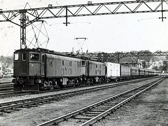
Passenger train in Nigel with a double traction locomotives 1E class, about 1930
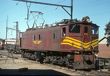
Class 1ES shunting locomotive emerged from the 1E E145

E25 in black in the depot in Danskraal , December 5, 2012


Individual evidence
- ↑ a b c d e f g h i j k South African Electrification. In: Mike's Railway History. Retrieved October 5, 2014 .
- ^ A b c E. Gysel: Electric locomotives for the South African State Railways . In: Schweizerische Bauzeitung . tape 83 , issue 10, 1924, doi : 10.5169 / seals-82756 .
- ^ A b Hugh Burns: SAR Class 1E electric locomotive. Sydney Electric Train Society Inc, August 2006, accessed October 5, 2014 .
- ↑ a b c Natal Contract to British . In: Electric Railway Journal . 61, January 13, 1923, p. 107. Retrieved September 15, 2010.
- ^ Rail electrification in Natal . In: Schweizerische Bauzeitung . tape 82 , no. 22 , 1923, pp. 291 .
- ^ South African Railways Power Plant . In: Electric Railway Journal . 60, No. 24, December 9, 1922, p. 914. Retrieved September 15, 2010.
- ^ H Brazil: The South African Railways Electrification . In: Electrical Substations . Edward Arnold & Co, 1928, p. 110 (Retrieved January 12, 2010).
- ^ A b c d e Leith Paxton, David Bourne: Locomotives of the South African Railways: A concise guide . Ed .: C. Struik. C. Struik, Cape Town 1985, ISBN 978-0-86977-211-9 .
- ↑ a b c d e f g h John N. Middleton: Railways of Southern Africa Locomotive Guide - 2002 . Beyer-Garratt Publications, Herts, UK 2002.
- ↑ a b South African Railways Index and Diagrams Electric and Diesel Locomotives, 610 mm and 1065 mm Gauges, Ref LXD 14/1/100/20, January 28, 1975, with appendices
- ↑ see also the article about electric locomotives in the section Driving and power control: direct current to explain the starting process
- ↑ a b Steam, Oil & Wires, vol 1, (Bernard Zurnamer), pp69-71
- ↑ Metropolitan-Vickers Gazette, December 1922 and March 1925 editions
- ^ Early Electric Loco History - Les Pivnic. Retrieved March 15, 2016 .
- ^ Early Electric Loco History - Les Pivnic. Retrieved March 15, 2016 .
- ^ Association of Rolling Material Directory Switzerland (Ed.): SLM Lokomotiven 1871–1984 . Union Verlag, Solothurn 1984, ISBN 3-907976-01-0 .