Swivel bending
Swivel bending is a manufacturing process . It is one of the main group of reshaping the group bend forming , where it together with the roll bending , roll bending and circulation bending to the subgroup of the bend-shaping with rotating tool is associated. There are pivotable folding beam used as a tool. The workpiece is clamped between the upper beam and lower beam. By swivel bending you can produce similar profiles such. B. by die bending . There the tool moves in a straight line. The method can be applied to a specific folding machine run or in fully automatic bending centers used.
Bending sequence for swivel bending
Although folding machines differ greatly in speed, flexibility and sheet thickness, they all bend in the same way:
- the stop and hold-up system positions the sheet metal made of steel or other metallic materials
- the upper beam clamps the sheet metal against the lower beam
- the bending beam bends the sheet metal to a desired angle.
The bending beam can be moved by hand or by motor power. Spindle , eccentric or hydraulic cylinder are used to clamp the sheets using the upper beam . The tools of the upper beam, the bending beam and the lower beam are interchangeable in order to be able to adapt the machine to different bent part lengths and bent part geometries.
Swivel bending is particularly suitable for bending flat sheet metal that is to be formed in the edge area. When bending, the sheet metal remains on the support system in the machine. The operator does not have to hold the weight of the sheet metal outside the machine, nor does he have to lift the sheet metal during bending and support the sheet metal weight after bending. A single operator can handle even large and heavy metal sheets on his own.
The operator loads, bends and unloads large parts from the rear of the machine using a backgauge that is extended on one side. He processes small parts from the front of the machine.
Sheet thicknesses and bending radii
Modern folding machines automatically adjust to the sheet thickness to be processed and the desired bending radius when the program starts. With thin sheet machines (up to approx. 2 mm) only the height of the bending beam to the pivot point is usually adjusted, whereby the machine adjusts itself to the sheet thickness. Above 2 mm, it is essential to adjust the bending beam and the lower beam (shifting the center of the radius) in order to achieve exact bending results and avoid cracking or material breakage. Sheet thicknesses up to 6 mm are used.
Advantages and disadvantages of swivel bending
- very short legs can be bent
- By lining up short segments, any radii can be bent (step bending)
- Open and closed envelopes can be bent
- Perforated sheets can be bent precisely because the sheet is clamped during bending
- Sheets with a sensitive surface can be bent because there is little relative movement between the tool and the sheet surface (stainless steel, coated sheet metal)
- low tool wear due to the low relative movement
- For different bending angles, bending radii, sheet thicknesses and leg lengths, only one universal tool set is usually required
- no additional angle measuring devices required
- the machines and tools can be used very flexibly. This results in low acquisition , maintenance and set-up costs .
- The process can be easily automated . It is often integrated into flexible manufacturing cells.
- The long processing times are a disadvantage. This is why swivel bending is mostly used in workshop production for small and medium batch sizes .
Retrofitting
Automatic tool clamping systems clamp the tools of the upper and bending beam as soon as the operator starts work. Together with graphic set-up instructions, even extensive tool changes are reduced to two to five minutes. With swivel bending, the working length is often divided into several stations in order to be able to complete bent parts with a single tool assembly.
programming
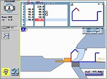
Modern CNC controls are easy to use. The operator draws the bent part on the screen with his finger. The user simply pulls a flexible leg to the desired dimension and angle. The control automatically determines a suitable bending sequence, shows the required development of the sheet (cut length ) and compensates for the springback of the sheet during bending. On the screen, the operator sees the finished part, every single bending step and the generated bending program.
However, the software for processing must be precisely set according to the selected material and the properties of the bending beams in order to create accurate developments of the part for punching or laser beam production. See more about this in the article on bending shortening .
accuracy
Precision of the bending angle
With folding machines, the bending beam swivels with an accuracy of 0.1 degrees and thus ensures precise and repeatable bent parts.
Precision of the bending legs
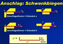
With swivel bending, the entire part and not the individual bending leg is hinged. This means that all inaccuracies in the cut in the first leg of each bending direction disappear. All other legs and especially the length and width of the part are dimensionally exact.
Tolerances in the sheet thickness
Tolerances in the sheet metal thickness do not affect the bending result, since the bending beam always takes the outside of the sheet metal as a reference.
Straightness of bend
The rigidity of the machine determines how straight the bends are. Thin sheet machines manage without crowning systems thanks to a deep bending beam . The use of crowning systems is common for thick sheet metal. They compensate for the deflection of the bending beam by increasing the center of the bending beam. A basic distinction must be made here between static and dynamic crowning. With a static crowning, the curvature of the upper, lower or bending beam that has been set remains the same throughout the entire process, regardless of the angle to be bent. However, since the springback force depends not only on the material thickness, the strength of the material, the rolling direction, etc., but also essentially on the angle to be bent, the curvature of the bending rail during the bending process must be changed accordingly in relation to the angle dynamic crowning possible. While in the manual version the crowning is usually adjusted by a dial, this process is fully automatic when using a hydraulic-dynamic crowning. Without manual rework, a correlation coefficient is derived from the main factors, sheet thickness and springback, with the help of which the corresponding crowning is derived for the sheet metal to be bent. The required data is recorded with the orthogonal factor analysis according to the Varimax method .
Workpiece range and areas of application
- Metal doors, furniture, shelves
- Transport facilities
- Advertising signs
- Electrical and electronic enclosures
- Air conditioners and boiler cladding , stoves
- Machines and machine covers
- Roofing and facade sheets, metal components
- Luminous body
- Restaurant and kitchen facilities
- Cleaning machines
- Medical equipment and facilities
- Vending machines
- Partitions
- Elevators and escalators
Web links
Individual evidence
- ^ Fritz, Schulze: Fertigungstechnik , Springer, 11th edition, p. 487.
- ↑ König, Klocke: Manufacturing Process 4 - Forming , Springer, 5th Edition, 2006, p. 406.
- ↑ Günter Spur, Theodor Stöferle: Handbook of Manufacturing Technology II / 3 system. Forming and cutting. Hanser Verlag 1985, pp. 1125f.
- ↑ Hoffmann, Neugebauer, track: Handbuch Umformen , Hanser, 2012, pp. 590f.
- ↑ Manfred Weck : Machine tools 1 - machine types and areas of application , Springer, 5th edition, 1998, p. 133f.
- ↑ Hoffmann, Neugebauer, track: Handbuch Umformen , Hanser, 2012, pp. 590f.
- ↑ Hoffmann, Neugebauer, track: Handbuch Umformen , Hanser, 2012, p. 591.


