
Servo valve
A servo valve is a variant of the proportional valve . It allows any position of the valve opening and thus the fluid - flow to. It differs from the simple proportional valve in the design of the piston control edges, with the help of which a larger bandwidth of the frequency response is achieved (also called "dynamics" in the industry). This makes servo valves very valuable, especially in control engineering. However, the precision required to manufacture them makes them expensive.
Designs
Servo valves are electromagnetically controlled proportional valves. They have pistons that produce the most linear possible dependency between control current and flow. Proportional valves have a dead zone in the zero crossing and their advantage lies in other areas. The advantage of servo valves is that they have no dead zone there. That is why the zero crossing is also fully used, i.e. on both sides, the positive and negative side, which means flow in both directions. Therefore, servo valves are at least three-way valves or higher-order directional control valves.
Single-stage servovalves are driven by an electromagnetic force and move a piston. There are two-stage servo valves , differentiated according to the functional principle, in a nozzle-flapper design (flapper servo or flapper-nozzle servo) and with a movable nozzle (jet pipe servo). Servovalves can be combined with larger medium-controlled proportional valves to form multi-stage valves. Medium-controlled servo valves are usually only available as a pre-installed main stage of a two-stage servo valve and not separately.
Examples
Single stage servo valve


The piston of the single-stage servo valve is moved directly by the spool. The drive is similar to a proportional valve. It is built in such a way that the coil (with the current Is) attracts the magnetically relevant superstructure on the piston in an approximately linear range. A spring works against this, here on the other side. In the de-energized state, the valve shown is not in the blocked state. The coil must be controlled at around 50% so that the piston moves to the center.
If the servo valve is driven by a linear motor or a torque motor instead of a coil, the piston can be actively moved in both directions. In the middle it has a currentless zero position in the locked position caused by springs.
Flapper servovalve


The flapper of a corresponding servo belongs to the first stage of the two existing valve stages. Furthermore, the 2 nozzles and the electromagnetic control belong to it. The second stage includes the piston of the servo valve. The baffle plate is placed in the middle between two closely opposite nozzles. It is influenced by the electrical control current of the servo valve and the valve piston of the second stage, and it influences the hydraulic fluid in the nozzles. The influence of the piston of the second stage is the negative feedback of the integrated mechanical control circuit , which ensures that the piston reaches the position required by the coil current and corrects it until this is the case.
If there is still no current flowing, the plate is in the middle or the control circuit quickly settles in the middle.
If a current flows like in the second picture, the armature exerts a force on the impact plate. A jet of liquid always comes out of the two nozzles. The plate leans towards a nozzle, here to the right, there the liquid can no longer escape unhindered. This increases the pressure in the line behind it. Since it is connected to the piston of the second valve stage, it moves to the left.


Now the control loop comes into play. The piston pushes the baffle plate back again via the spring, until it has restored the balance between the left and right nozzle and the piston no longer moves. The baffle plate strives to always be in the middle. The deflection of the piston is therefore proportional to the electromagnetic force emanating from the armature, here about half an opening of the valve. If the current changes, the piston follows accordingly.
Of course, this also applies in the event that the power goes out, as in the second picture. The line at the left nozzle has increased pressure and pushes the piston to the right. This goes on until it settles into the basic position.
Zero point adjustment


The flapper servo valve thus has a mechanical zero point that is set when there is no current. In this state, the working line connections A and B should also be blocked. Since the valves mentioned have a matching sleeve around the piston for reasons of precision, the zero point can be set with them.
You can move the sleeve, as shown here to the left. The valve is in operation so that the flow can be controlled. If a cylinder is connected directly behind it, its movement for flow measurement can also be observed; if another valve is connected, the movement of the piston of this indirectly controlled valve can be measured.
Measure and regulate
A servo valve can have internal mechanical control if 2 stages are involved. The piston position can also be monitored, even with single-stage servo valves. Usually this is done with non-contact differential transformers (LVDTs). With this information, an electrical control loop can be built. If available, it is superordinate to the mechanical control loop and provides it with the calculated setpoint. The electrical control is limited to reaching the desired piston position as quickly and precisely as possible. It can also correct an incorrect zero point setting, but it takes a short time and only works with the power available.
The piston position control does not exclude a further higher-level control. It could check the cylinder position and correct it in the event of deviations between the setpoint of the drive controller and the actual value.
Zero overlap of the piston control edges
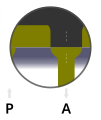
Idle state

postponed


The control edges are the parts on the valve piston that close or open the openings to the working line connections A and B. You are ultimately responsible for the flow through the valve. The piston of servo valves is shaped in such a way that in the idle state it lies exactly above the working line opening, here it is above A. The piston or the notches it contains are edge to edge with the edge of the working connection. With the slightest movement of the piston, the hydraulic fluid begins to flow in the working connection, here into outlet A.
Modular construction

Servo valve with mechanical feedback

Servo valve with electrical feedback
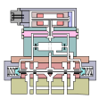
Servo valve with barometric feedback


In practice, servo valves - as shown in the figures - have a modular structure. This makes it possible to standardize individual components and to assemble servo valves according to the modular principle - optimized for the respective application.
application
Due to the precision of a servo valve, which is usually required in practice, servo valves are among the most expensive valve types on the market. For this reason, servo valves are only used for special applications, for example when a proportional valve is not sufficient. In addition, they always use some hydraulic fluid during operation, even without anything moving. Servo valves are used, for example, in power steering in cars or in controlling tail units in an aircraft , as well as in various positioning tasks in hydraulic drive technology .
Individual evidence
- ↑ http://www.boschrexroth.com/business_units/bri/de/products/05_stetigventile/index.jsp ( page no longer available , search in web archives ) Info: The link was automatically marked as defective. Please check the link according to the instructions and then remove this notice.
- ↑ Data sheet 4/3-way servo solenoid directional control valves..4WRLE 10 ... 35 ( Memento of the original from July 9th, 2015 in the Internet Archive ) Info: The archive link was automatically inserted and not yet checked. Please check the original and archive link according to the instructions and then remove this notice. (PDF; 1.4 MB), Bosch Rexroth, section Symbols, page 3. Three volume flow characteristics of a two-stage hydraulic servo valve with different slopes and inflection points, but always without a horizontal dead zone
- ↑ Data sheet 4/4 directional control valves, directly controlled..4WRPEH 10 (RE 29037) ( page no longer available , search in web archives ) Info: The link was automatically marked as defective. Please check the link according to the instructions and then remove this notice. , Bosch Rexroth, 2012. Via a directly controlled hydraulic servo valve with a coil and a displacement transducer
- ↑ Catalog extract Direct Drive Servovalves D633 / D634 (PDF; 782 kB), Moog Inc., 2009. About a directly controlled hydraulic servo valve with symmetrical linear motor, with sectional view
- ↑ Data sheet Electrohydraulic Servovalves HVM 090 ( Memento of the original from March 4, 2016 in the Internet Archive ) Info: The archive link has been inserted automatically and has not yet been checked. Please check the original and archive link according to the instructions and then remove this notice. (PDF; 338 kB), Schneider Kreuznach, 2003. Via a directly controlled hydraulic servo valve with a symmetrical torque motor, with sectional view
- ↑ Datasheet Electropneumatic Mass Flow Servo Valves - PVM 025 / PVM 027 ( Memento of the original from March 4, 2016 in the Internet Archive ) Info: The archive link was inserted automatically and has not yet been checked. Please check the original and archive link according to the instructions and then remove this notice. (PDF; 1.9 MB), Schneider Kreuznach company, 1992. Via a directly controlled pneumatic servo valve with a symmetrical torque motor, with sectional view
- ↑ DSP Control of Electro-Hydraulic Servo Actuators (PDF; 588 kB), by Richard Poley, Texas Instruments, 2005, chapter Flow Control Servo-Valve, Figure 9: Valve Responding to Change in Electric Input, page 10. Sectional drawing and description of a two-stage hydraulic flapper servo valve
- ↑ Hydraulic Proportional and Closed Loop System Design (PDF; 4.7 MB), by Neal Hanson .., Bosch Rexroth AG, 2011. Product overview of proportional and servo valves. Page 47ff: Scheme of a two-stage hydraulic flapper servo valve with characteristics, control instructions, product selection criteria.
- ↑ Hydraulic servo systems ( Memento of the original from May 20, 2014 in the Internet Archive ) Info: The archive link was inserted automatically and has not yet been checked. Please check the original and archive link according to the instructions and then remove this notice. (PDF; 1.6 MB) by Karl-Erik Rydberg, Organization: Linköpings universitet, 2008, Chapter 3.3: Examples of electro-hydraulic servo valves, Figure 3–9: Valve responding to change .., page 13. Sectional drawing and description of a two-stage hydraulic flapper servo valve
- ↑ CHAPTER 12: Infinitely Variable Directional Valves , 2007, Website Hydraulics & Pneumatics, Figure 12–11: Flapper-design servovalve. Zero adjustment with the help of a sleeve on a two-stage hydraulic flapper servo valve, with sectional drawing and description
- ^ Coverage: Dieter Will .., Hydraulics - Basics, Components, Circuits, e- ISBN 978-3-642-17243-4 , page 253