Image frequency
The image frequency , also the image reception frequency , denotes the undesired second reception frequency at a distance of twice the intermediate frequency f ZF from the desired reception frequency in the case of mixer stages as used in heterodyne receivers.
In the case of radio receivers, a mostly disruptive image frequency reception can be suppressed by
- sufficiently low bandwidth or high selection of the reception frequency range by means of input-side bandpass filters between antenna and mixer or
- Compensation according to the phase method .
In addition to heterodyne receivers for radio reception, the effect of the mostly unwanted image frequencies generally occurs in all devices with mixer stages for frequency conversion. This includes, for example, measuring devices such as the spectrum analyzer .
root cause
In the heterodyne receiver, the receive frequency is mixed with the frequency of the local oscillator to a mostly lower intermediate frequency and processed there:
The reason is that the range around the lower intermediate frequency can be further processed more easily, since there is only a fixed frequency range that is independent of the reception frequency. In order to avoid the so-called inverted position of the spectrum in the intermediate frequency during downmixing, the frequency of the local oscillator is selected to be lower than the receiving frequency . However, the mixer also multiplies the receive frequency (image frequency ) , which is symmetrically below the frequency of the local oscillator, and uses this to generate in the inverted position:
The two spectra are superimposed to form the sum spectrum of the intermediate frequency
and can no longer be separated. It is therefore necessary to suppress the interfering image frequency before mixing, for example with an upstream bandpass filter. The bandpass filtering is outlined in the spectral representation with the area highlighted in yellow.
- example
- If the local oscillator generates the frequency 2.0 MHz, the two frequencies can be used with an intermediate frequency of 455 kHz and no preselection
and
are received in overlay. Both reception frequencies differ by .
Image frequency spacing
In the case of downmixing, the intermediate frequency is below the frequency of the local oscillator. In this case the image frequency spacing is
and corresponds to twice the intermediate frequency.
If the intermediate frequency is above the superimposition frequency, this is the case with upmixing, the image frequency spacing is
Image frequency attenuation
The ratio of the signal at the reception frequency and at the image frequency is used as image rejection or image rejection referred to and belongs to the far-off. For professional receivers, values between 60 and 70 dB are common, in entertainment electronics devices the values can be significantly lower.
Phase process
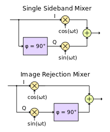
With every mixing process, two side bands and . The unwanted frequency band can be eliminated with the IQ method using complex-valued signal processing without the use of filters made up of resonant circuits. To do this, you add another signal to the mixed signal, which is phase-shifted in the frequency range to be deleted . This is added or subtracted from the first mixed signal - depending on which of the two mixed frequencies you want to cancel.
As shown in the figure, you need a local oscillator that outputs the local frequency in addition to the reference phase position with 0 ° and rotated by 90 ° - this fact is expressed in the graphic with the terms sin (.) And cos (.). Furthermore, two separate mixing stages are necessary. In addition, you need a link to rotate the phase by 90 °. This phase shift over the entire spectrum is implemented by means of a Hilbert transformation , shown in the figure as a purple block. The addition or subtraction of the two mixed signals formed in this way, which in principle represent the real and imaginary part (I and Q) of an analytical signal , then either cancels or eliminates, comparable to constructive or destructive interference in the field of physics.
Due to the Hilbert transformation required, which can be implemented as a digital FIR filter to a good approximation, the method is particularly suitable for applications in the field of digital signal processing and is used, for example, in software defined radio (SDR). Similar methods are also used for mixer stages in the range of a few 10 GHz with low-noise signal converters (LNB).
literature
- HH Meinke, Friedrich-Wilhelm Gundlach : Pocket book of high frequency technology. 5th edition, Springer, Berlin, 1992, ISBN 3-540-54717-7 .
- H.-J. Pietsch: Shortwave amateur radio technology. Franzis, Munich, 1979, ISBN 3-7723-6591-4 .


