
Coil winding technology
In the electrical industry, coil winding technology refers to the type and method of winding the electrical conductor (insulated wire or stranded wire) into a coil .
The resulting geometric structure consisting of one or more turns or layers creates a concentrated electrical property in its entirety: coils can be used as actuators ( electromagnets , transformers , motors , voice coils, rotating coils, etc.) or as sensors (antennas, dynamic microphones, measuring devices, etc.) .) can be used. The windings of actuators, such as. B. the stators or rotors of motors are also referred to as coils. The winding technology essentially determines the properties of electromechanical assemblies with windings. This includes the insulation strength, the quality factor , the size required for a specific power or magnetic force or the magnetic stray field. Because the demands on energy efficiency are increasing, so are the demands on the development of components for electromechanical assemblies such as B. in electric motors.
The winding technology is divided into several groups based on the type and geometry of the coils to be wound.


Process engineering basics for winding structure
Definition of terms fill factor
For miniaturization and material savings (e.g. copper) it is often necessary to keep the geometric dimensions of a coil as small as possible. The amount of electrical conductors, including their insulation layer, introduced into the available winding space is referred to as the mechanical fill factor .

To determine the fill factor , the sum of the conductor cross-sections including their insulation is related to the available winding cross-section:


- - Wire diameter including the enamel insulation
- - number of turns
- - Window cross section of the coil former ( English coil former )


In the case of round wires, it can be seen that an orderly structure of a winding (almost tightest circular packing of the wire cross-sectional areas) has fewer air spaces in the winding, i.e. H. causes a higher fill factor and thus a higher efficiency of the electrical component. In addition, the heat dissipation from the winding is improved.
An optimally executed winding, in which the wires of the upper winding are at least 300 ° of the circumference in the valleys of the lower winding and thus occupy approximately the closest circular packing there, is called an orthocyclic winding . In contrast, the unordered winding of electrical conductors in the winding room is called a wild winding .
Since a round wire always includes spaces that are not electrically effective, the fill factor will always be less than 1. To achieve a particularly high fill factor, rectangular and flat wires are used, which are wound flat or on edge.
Wild winding
With this type of winding structure, no optimal fill factor is achieved. The spread of the applied wire length and thus the coil resistance is also relatively large. Wild windings are usually produced homogeneously by laying the wire with a 1.5 to 3-fold pitch compared to the wire diameter during winding. This is also intended to prevent turns from slipping down into the sub-winding, which can lead to large voltage differences and thus to electrical breakdowns.
Despite many disadvantages, this method can be considered the most common and economical, especially in mass production. It is characterized by the fact that there are no high demands on the machine or operator and the windings can be applied at a very high speed. The main areas of application for wild windings are contactor and relay coils, small transformers, ignition coils , etc., i.e. components with relatively thin wires up to approx. 0.05 mm in diameter.
The fill factors achieved when using round wires are approx. 73% and are thus around 80% of the fill factor of an orthocyclic winding (90.7%).
The winding height results approximately from the equation:


- - wire diameter over lacquer (CuL)
- - Number of turns
- - wrap width

Helical winding

The wires lie helically in each position. Since the ease of movement changes from layer to layer between right and left, the wires cross and spontaneously lay in the gaps of the previous layer. There is no wire guide through the lower layer. The wrap gets mixed up in many layers - a wild wrap is created. This can be countered with layer insulation, which is often necessary anyway when the layer voltage exceeds the insulation strength of the enamelled copper wire.
Orthocyclic winding


With this type of winding structure for round wires, the optimal fill factor is generated (90.7%). The aim is to place the turns of the upper winding in the valleys of the lower winding (similar to the Lebus grooving on crane rope drums). If you put three circles one inside the other, it shows that the smallest possible space requirement results under a 60 ° arrangement. From this it can be derived mathematically how large the ratio of the proportion of the total space used to the proportion of the circles is.
The best way to utilize space is essentially about winding the largest possible circumferential portion of a turn parallel to the coil flange so that this condition persists as long as possible. If the turn then meets the previously incoming wire, the wire must complete a winding step the size of the wire diameter. This winding pitch range can spread over an angle of up to 60 ° to the circumference of a round coil or, in the case of rectangular coils, over a rectangular side on the winding base in the first layer, depending on the wire diameter and coil diameter and, above all, the winding width. If this is not the case, the self-guidance behavior is lost and a wild winding forms. Ultimately, the incoming wire mainly influences the position and quality of the coil jump. It is important to ensure that the wire enters the winding area at as flat an angle as possible. This prevents the wire from tending to bulge due to unnecessary deflections and thus taking up more space than necessary for the second turn. In the case of orthocyclically wound coils, the winding jump area is always located at the same point, namely in the area of the wire inlet, and continues in a helical manner, opposite to the winding direction. This means that the larger the winding width of a coil, the larger the winding jump area that emerges along the circumference. This resulting offset of the winding jump has the consequence that the point at which the wire pushes up at the end of the first layer into the second layer is at a different point than the wire entry point. This property is repeated with each wound layer, so that a spiral-shaped layer jump area (crossover) emerges on the side of such a coil.
From the fact that there are wire crossings in the layer jump area, it can be deduced that the resulting winding height is larger in this area. This is why orthocyclically wound coils with a round coil base are never round in the area of the last layer. The radial, constantly moving jumps in turns and layers create a hump-shaped formation at this point. The constantly changing radially changing intersection area means that the winding height at this point is not equal to the number of layers times the wire diameter. Experience has shown that, depending on the winding width, coil diameter and wire diameter, this intersection area is 5% to 10% greater than that in the layer area.
Position and size of the layer jump area (crossover)
Since the turns of a winding should be parallel as long as possible, i. H. the orthogonality conditions are to be fulfilled, it is necessary to match the winding width exactly to the number of turns to be wound per layer. Particularly in the case of angular coil cross-sections, efforts are made to keep the hump-shaped markings on the winding head side as a result of the layer jump, i.e. H. on the narrow side of the coil. The reason is often that square coils are blocked, used in a stacked laminated core or as a single pole in a circular arrangement. The coils should therefore be as narrow as possible so that there is no contact with the neighboring coil or the laminated core. With orthocyclic windings, three different winding geometries are specified for both round and square coils:
a) Same number of turns per layer

b) unequal number of turns per layer, starting with the shortened layer

c) unequal number of turns per layer, starting with the stretched layer

The choice of the winding structure to be used essentially depends on the construction of the coil or the coil former. Among other things, it must be taken into account what space is available in the winding width and in the winding height. With a clever choice of the winding scheme, it is also possible to influence the location and end of the last winding. The winding height of an orthocyclic winding results from the following equation:
![h = [1+ (n-1) \ times \ sin 60 ^ \ circ] \ times d](https://wikimedia.org/api/rest_v1/media/math/render/svg/ff8d1ce8cc54ffe9cae52cb7a21f1817632414ca)
- - winding height
- - Number of layers
- - Max. Wire diameter over lacquer (CuL)
Since with the orthocyclically wound coil over min. 300 ° of the circumference of the winding layers the tightest circular packing of the wire cross-sections exists, this winding method achieves the highest fill factor and is the best way to fill the available winding cross-section with round wires. For angular coils, this is considered to be orthocyclically wound if the turn and layer jump only occurs on one of the sides of the winding cross-section. Theoretically, a geometric fill factor of 0.91 is achieved. The value is not achieved in practice because there is a winding jump and layer jump area and the wire insulation is not taken into account.


Fill factor = = =


- = 0.907

Basically, it can be stated that the requirements to be met for orthocyclic windings are very high. The summation of all tolerances must be kept very small. The following values are indicative:
a) Tolerance of the winding window width

- - Tolerance of the winding window
- - Max. Wire diameter over lacquer (CuL)

b) Tolerance of the wire
the max. Wire diameter tolerance should not be greater than

- - Diameter tolerance of the wire
- - turns per layer
- - Nominal wire diameter over lacquer (CuL)

This corresponds to about half the wire tolerance as specified in DIN46435
Manufacture of orthocyclic windings
Even if the requirements for low tolerances in the wire and the winding space were to be met with a correspondingly high level of technical effort, the problem would still remain that the wire guidance on the machine side must follow the winding structure described above even at high winding speeds. This is hardly possible in practice at high winding speeds, since z. B. at 18,000 turns per minute of the wire guide at a z. B. 0.3 mm thick wire would have to make a winding step in just 0.7 ms. The problem is compounded because in practice the ideal wire is never absolutely straight. These irregularities and curvatures, resulting from the winding of the wire on delivery reels, mean that the wire never lies against one another absolutely according to its actual diameter, but at a distance according to its irregularity.
This gap formation when the wire is wound up is influenced by the surface properties of its lacquer layer, for example the sliding behavior, as well as the elongation behavior or the rigidity of the copper. The wire stretch may be between 6% and 3% depending on the wire diameter and the supplier. Practice shows that an orthocyclic winding can be produced well if the wire elongation (elongation leads to straight wire) is initially selected to be very high. For the reasons described, it is therefore impossible in practice to determine an exact pitch for the wire guide in accordance with the wire diameter.
These unpredictable conditions at the beginning of the winding are counteracted by the wire, i.e. H. every single turn of the first layer on the inside diameter of the coil, forces it into a predetermined position. The wire lies in a prefabricated groove geometry of the spool; the wire guide does not need to follow exactly, but only approximately. Since the wire always loses its cross-sectional area during winding due to the wire tension to be used and the necessary deflections (mechanical stresses under tensile load), the distance between the grooves is only limited to the max. occurring wire diameter. The effects of curvatures and tolerances of the wire and the coil body as well as changing surface properties can thus be avoided. In particular, curvatures of the wire that occur as a result of wire deflections, such as. B. pulleys, wire eyelets or even the wire guide nozzle within the wire feed of a winding machine, can lead to deformations remaining on the winding of a coil. A grooving of the winding base supports the exact position of the wire during the winding process. This behavior is particularly advantageous in winding processes in which plastic deformation of the wire is unavoidable immediately before the wire is deposited on the winding base. This behavior can be observed in particular with needle winding technology. For physical reasons, it is unavoidable here that the wire exits the wire guide nozzle at an angle of approx. 90 °. This means that mechanical tensions remain in the wire, which become visible in the form of a turn curved on the winding base. The following threads or the following layers can change in their desired position.
From the second layer onwards, laying is made easier because the wire is guided through the spaces between the previous layer. If the deflection is not too great, the wire now runs alone and with a constant number of turns per layer. For the wire guide movement, this means that the tracking must be more precise the smaller the distance between the wire guide nozzle and the spool. Under certain circumstances, a laying movement can be completely dispensed with if the distance between the nozzle and the coil is so great that the force component no longer has any effect, contrary to the self-guiding behavior of the wire. Due to the self-guiding behavior of the wire, it is possible that the wire guide can run continuously even with orthocyclic winding and does not have to follow step by step.
Design of an orthocyclic winding
The layout of the space required by an orthocyclic winding is usually carried out using an iterative procedure. First of all, the specified parameters of the required number of turns, the required wire cross-section and the maximum available space of an insulated coil are used for the calculation basis.
Calculation example
An orthocyclic winding design for a round coil with 150 turns with a wire diameter of 0.3 mm and a maximum winding width of max. 9 mm can be calculated. The winding diameter in the winding base is 8 mm.

Given:
Wire Ø Cu 0.3 mm → CU1L = 0.334 mm (table value)
Coil width: should be 9 mm // 150 turns, coil inside diameter 8mm.
a) Calculation of the winding width
In the first iteration step, a winding with the same number of turns per layer is used.
9 / 0.334 → 26.9 turns / layer → selected 26 turns / layer

b) Calculation of the number of layers
Number of layers = 150/26 = 5.76 layers
c) Calculation of the winding height
![{\ displaystyle {\ text {Winding height h}} = [1+ (n-1) \ cdot \ sin 60 ^ {\ circ}] \ cdot d}](https://wikimedia.org/api/rest_v1/media/math/render/svg/af218b0fdaaf8dd9670ceecbfc1500148fe4714c)
![{\ displaystyle {\ text {Winding height h}} = [1+ (6-1) \ cdot \ sin 60 ^ {\ circ}] \ cdot 0 {,} 334 \, \ mathrm {mm} = 1 {,} 78 \, \ mathrm {mm}}](https://wikimedia.org/api/rest_v1/media/math/render/svg/c5c03ab4b748e66bdaf18602471418daa8837bcc)
d) Calculation of the winding height in the layer jump area


e) Calculation of the outside diameter of the coil


f) Calculation of the outer dimension of the coil in the layer jump area


Summary of the result: The calculation has shown that the space requirement of the pure orthocyclic winding with enamelled wire fills a rectangular area with the dimensions 1.86 mm × 8.85 mm. Assuming that it is a round coil with an inner diameter of 8 mm, the outer diameter is 11.72 mm. The winding space delimitation (flanges of a coil former) of a winding carrier must have a diameter of at least D min = 11.72 mm, taking into account the layer jump area .
Calculation of the fill factor
The fill factor is a measure of the ratio between the volume of a winding package and the volume required for this to accommodate the winding package. To do this, it is necessary to take into account the space required by the rotation diameter of the spool in the "crossover" area.

a) Calculation of the mechanical filling factor The imaginary space with the dimensions 8.85 mm × 1.86 mm has an area of 16.461 mm². The sum of the partial areas of the isolated turns have an area of

A = sum of the partial areas of the insulated wire
D L = wire diameter over lacquer
n = number of turns


b) Calculation of the electrical filling factor The imaginary space with the dimensions 8.85 mm × 1.86 mm has an area of 16.461 mm². The sum of the partial areas of the uninsulated turns have an area of
A = sum of the partial areas of the non-insulated wire
D Cu = bare wire diameter
n = number of turns


Winding process
Linear winding technology
With the help of the linear winding process, an electrical coil or winding is generated by winding the wire by rotating the coil body to be wound, the component to be wound or the device that carries or forms the coil. The wire is often pulled overhead from the supply roll, which contains up to 400 kg of enamelled copper wire, i.e. over the edge of the upright stationary roll. The wire is usually fed through a tube. Before the actual winding process, the wire is attached to a post or a clamping device of the bobbin or winding device.
As a result of the linear laying movement of the wire guide tube for the rotational movement of the component to be wound, the wire is distributed in the winding space of the coil former. The rotational movement as well as the laying movement is made possible with the help of computer-controlled motors. In relation to one revolution of the axis of rotation, depending on the wire diameter, the laying axis of the wire guide tube is moved accordingly (laying gradient).
In doing so, speeds of up to 30,000 1 / min are achieved, especially when processing thin wires. Depending on the winding diameter, wire speeds of up to 30 m / s can be achieved during the winding process. The components to be wound are taken up on so-called winding devices. The winding devices are in turn coupled to driven spindles that generate the rotary movement. Since the wire should be applied as evenly as possible into the winding space, the axis of rotation and the laying axis must work synchronously during winding.
In order to be able to control the positions of the wire guide nozzle relative to the component to be wound even with different component geometries, three CNC axes are generally used to move the wire guide nozzle.
This also enables the connection to the coil body posts (the posts are also used for contacting by soldering or welding): by letting the three axes move towards one another in such a way that the wire guide nozzle moves in a helical manner around the winding post, it is possible to start - or to fix the end wire of a coil by the so-called termination. So that the wire does not relax when changing products, it is attached to a wire parking pin on the machine.
This wire parking pin can either be a clamp or the image of a post that is wrapped around the spool as in a termination process. Before starting to wrap, after terminating the start wire post, the wire to the parking pin must be separated. This is done by tearing or cutting, depending on the wire thickness.
Enamelled copper wires can usually be torn up to a diameter of approx. 0.3 mm by running a tear pin or the wire guide nozzle itself close to the post of the coil. The separation point should be close to the post of the coil so as not to hinder a subsequent contacting process (soldering, welding, etc.).
Since all motions are passed during winding on CNC axes, it is possible, wild windings orthocyclic windings or winding other geometries (for example, cross-wound coils produce). The wire guide control can often be switched between continuous and incremental movement.
As a result of the separation between the wire guide and the rotation of the component to be wound, the arrangement of the product and the wire guide can be duplicated in linear winding technology. So it is possible on z. B. to wind 20 spindles at the same time. This makes the linear winding process a very efficient process, since the cycle time for the production of a component results from the quotient of the cycle time of a winding process and the number of spindles used. The linear winding technology is often used efficiently where low-mass bobbins are wound.

Linear winding
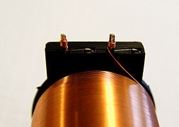
Wrap-on post on a spool
Wire parking pins on winding machine

Linear winding machine from Aumann GmbH


Flyer winding technology

In the "flyer" winding technology, an electrical coil or winding is generated by feeding the wire over a roller or through a nozzle that is located on a "flyer" (rotating disc), which is at a certain distance from the coil rotates. The wire is fed through the shaft of the flyer. For winding, the component to be wound must be fixed in the winding area of the flyer. It is necessary that the wire is fixed outside the flyer at all times during the winding process. The fixation of the wire is usually made possible by the so-called sequential winding process (often used on rotary indexing tables): There are wire clamps or wire deflectors on the circumference of the table, which enable the wire to be pulled along and thus fixed. This enables components to be changed very quickly, since the wire does not need to be stored separately in a wire clamp on the machine.
Since the last point of the wire is on a nozzle or roller of a flyer arm, which moves on a fixed circular path that can only be shifted in the direction of laying, precise laying close to the coil surface is not possible. This results in the fact that it is not easily possible to specifically fix or even terminate start and end wires on the component to be wound. However, it is entirely possible to produce orthocyclic coils using the flyer winding process. A self-guiding behavior of the wire on the coil surface is advantageous here.
Since the component to be wound only has to be presented in the winding position and otherwise no movements whatsoever need to be carried out during the winding process, very misshapen and bulky products can also be produced. An example are anchors of electric motors (armature winding technology, special form of the sequential winding process): The wire is held in a clamp attached to the machine while the component is being changed. Since the rotors often consist of heavy, punch-stacked sheets, the flyer winding technology is particularly advantageous here. Since the flyer cannot be guided directly with rotor or armature winding technology, the wire is guided over polished guide jaws into the corresponding slot. Special wiring sleeves ensure the correct wire position at the connection points of the commutator .
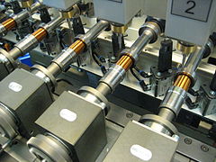
Needle winding technology


In order to efficiently wind the closely spaced pole shoes of electronically commutated multi-pole three-phase motors, they are provided with insulation and wound directly using needle winding technology. A needle with a nozzle, which is arranged at right angles to the direction of movement, moves in a lifting movement past the stator packs through the slot between two adjacent poles of the motor in order to deposit the wire at the desired location. At the turning point at the end winding, the stator is then rotated by one tooth pitch so that the previous process can run again in reverse order. A desired layer structure can be realized with this winding technique. The disadvantage is that there must be a free space between two adjacent poles, the size of which at least corresponds to the nozzle diameter. The nozzle diameter is approximately three times the diameter of the winding wire. The space between two neighboring poles can therefore not be completely filled.
The advantage of needle winding technology is that the needle carrier on which the wire guide nozzle is located is usually coupled to a CNC coordinate system. This enables the nozzle to move in three dimensions to the stator. It is thus possible to carry out a laying movement in addition to the normal lifting movement and the rotation of the stator. Targeted laying down of the wire is, however, only possible to a limited extent, as the wire is pulled out of the wire guide nozzle at an angle of 90 °, creating an undefined bulge.
The 90-degree deflection of the wire when it exits the hollow needle puts a lot of strain on the wire and often makes it difficult to sensibly wind copper wires over 1 mm in diameter. Ortho-cyclic winding is therefore only possible to a limited extent with a needle winder for these winding tasks.
Since the wire guide nozzle can be moved freely in space, it is possible to terminate the wire at contact points with an additional swivel device for the nozzle. As with conventional linear winding technology, a contact pin or hook flag can be terminated for the electrical connection and for connecting the individual poles to form a star or delta connection.

Drive scheme needle winding machine; patented connecting rod drive from Aumann
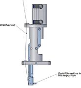
Winding nozzle in winding position

Winding nozzle in termination position


To ensure that the needle does not touch the slot when it moves up and down, precise synchronization of the rotational movement with the stroke movement is necessary. Influencing variables for the maximum winding speed are u. a. the stroke of the needle, the angle of rotation of the stator (number of poles), the wire diameter as well as the slot width and the helix angle for obliquely grooved stators. The mass of the wire guide and the needle carrier experience a high acceleration. This can lead to undesirable vibrations that affect the quality of the winding. The stroke movement is usually generated by recirculating ball screws. Servo drives must constantly reverse in order to reverse the needle movement.
Another way of initiating the stroke movement is the use of a crank disk, which can also have stroke adjustment and thus uses the advantage of the sinuid sequence of movements without having to reverse a drive motor. Up to 2500 strokes (turns) per minute are achieved.
With needle winding technology, it is possible to produce a finished assembly, for example stator coils, interconnection and contacting on one machine. Apart from the not fully used space between the poles, in contrast to the conventional drawing-in technique, it is possible to wind motor coils with a good fill factor even on low stator lamination heights (winding head heights).
Toroidal winding technology

With the help of the toroidal core winding technology, an electrical coil or winding is generated by winding an electrical conductor (e.g. copper wire) through the circular ring over the circumference ( toroidal transformer , toroidal core choke).
Before winding, the toroidal core is clamped in a receptacle, which can initiate a slow rotational movement on the core at mostly three rubberized contact points. A wire storage ring (an orbital wheel ) arranged at 90 ° to the toroidal core is now opened on the circumference and inserted into the center of the toroidal core. Wire is now wound onto the wire storage ring that is closed again. When the required amount of wire is available on the wire storage, the wire end from the wire storage is attached to the toroidal core to be wound. The simultaneous rotation of the toroidal core and wire storage ring creates a winding that is distributed around the circumference of the toroidal core. After completion, the wire storage must be opened again in order to be able to remove the completely wound toroidal core. Since the start wire and the end wire can often not be fixed to the toroidal core, toroidal core winding machines can only be automated to a limited extent.
Toroidal cores are used despite the high manufacturing effort (a lot of manual work) due to the low magnetic leakage flux , the low iron losses and the good power density. A possible quality feature of transformers is the uniform distribution of the windings along the circumference (low stray field). The isolation between different windings can be solved very differently. In the case of overlapping windings, a film is applied after the first winding to achieve good stray field properties. This must be wrapped over the circumference. Toroidal core winding machines with special magazines can also be used for this purpose.
Winding technology for motor coils
Trends in motor winding technology

Because of the higher power density, brushless EC drives (electronically commutated motors) with permanent magnet rotors are increasingly being used instead of asynchronous technology. Thanks to the compact design, the copper content can ideally be halved. The manufacturers of electric motors also demand more flexibility in production technology. Usually, pull-in systems are used for the production of asynchronous motors, which first wind air coils and then pull them into the stator with the help of a tool. The concentrated winding of EC stators, on the other hand, is more flexible in the manufacturing process, more energy-saving in use, better controllable and less space required.

Motor winding technology from the point of view of energy efficiency
In 1999, voluntary labeling (EFF classes; EFF = Efficiency) for electric motors was introduced in Europe. This classification was replaced by the IE classification in 2008.
(IE = International Efficiency)
- IE1 (Standard Efficiency)
- IE2 (High Efficiency)
- IE3 (Premium Efficiency)
- IE4 (Super Premium Efficiency)
The IEC / EN 60034-2-1 stipulated new rules for the test procedures to be used to determine motor losses and efficiency levels. It requires more precise efficiency values. The resulting degrees of efficiency differ from those of the previous test standard IEC 60034-2: 1996. Thus, the efficiencies from the different test methods cannot be compared with one another. For this reason, engine manufacturers are motivated to develop new generations of engines, such as B. EC motors to bring on the market. The manufacturing process for EC motors thus directly influences the winding technology used. In the course of the now affordable power electronics and the stable prices for magnetic materials such as neodymium and dysprosium from 2013 onwards, EC motors are increasingly being used compared to asynchronous motors.

Price development of neodymium oxide (source: Sachwerte purchase group, as of March 10, 2014)
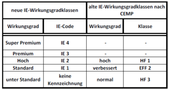
Comparison of the energy efficiency classes of electric motors in Europe (IE classification)
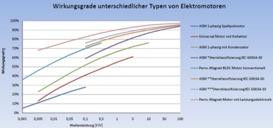
Efficiencies of different types of electric motors


These properties are particularly advantageous in the area of low-voltage applications. This is where thick wires with a small number of turns come into play. The stator design ranges from the unsegmented stator, the pole star with yoke ring, the stator with full pole segments to the pole chain.
Manufacturing process of distributed windings
Asynchronous motors with a distributed winding have been the largest part of electric motors worldwide for some time. The asynchronous machine with a distributed winding is particularly popular in automotive engineering, especially in the field of electromobility. Due to the long history of the asynchronous motor, the manufacturing process, the pull-in technique, is widespread. In the case of distributed winding, in contrast to concentrated winding, not every single tooth pole is wound, but coils are inserted into the stator slots over several tooth poles. Due to the fact that a winding that has already been introduced, because of its chord-like position of the coils, conceals other stator slots that are to be equipped with coils, it is often necessary to pull in a complete winding strand of one phase at the same time.

Coil pull-in machines pull prefabricated coil groups into the stators of electric motors. The coil groups are often produced on flyer winding machines and placed on the insertion tool with a transfer tool. In small series production, the coil groups are manually transferred from the winding templates to the insertion tool using transfer tools. The coil groups are then inserted with the pull-in tool in the previously placed stator, the grooves with z. B. insulation paper were isolated, withdrawn. Due to the fact that the diagonal winding of the coils into the slot of the stator, the inner width of the coils must be larger than the stator height, the large winding head typical of the pulling-in technique is created.

Due to the relatively loose winding in the stator slots as a result, it is necessary to close the slot openings towards the center of the stator with a so-called cover slide. In many cases this is possible together with the pull-in movement of the coils. Due to the fact that the conductors of the coils have to pass through an often narrow slot, the coils consist of a certain number of small substitute cross-sections that are later connected in parallel. This measure can also produce large conductor cross-sections.
Another reason for using many thin parallel-connected conductors is to avoid a so-called skin effect . In order to keep the effects of this effect as small as possible, cables with the largest possible surface are used in high-frequency technology, for example in the form of thin replacement cross-sections or strands. The low losses of strands are partly due to the fact that a large part of the inner surface participates in the flow of current. In electromobility in particular, it often happens that the motor is operated using a high-frequency voltage. Under certain circumstances, when using large conductor cross-sections, this can lead to high losses and undesired heat development in the stator winding.
After the winding has been drawn in, the stator or winding heads must be reworked. As a rule, the large number of connection cables are first separated manually and bundled according to the phases. In the further course of the finishing process, both winding heads are tied off with adhesive tape or tape. When using high operating voltages, the partial windings of each individual phase must be isolated from the respective neighboring phase with a foil or insulation paper. So that the winding heads are only located in the area of the stator back, both winding heads must be formed. This is done either through the use of a baked enamel wire under a bonding current connected during the forming process or through cold forming in connection with a subsequent impregnation. The creation of a specific winding head shape allows the rotor to be assembled or the stator to be inserted into a housing.

Tied winding head after the pulling-in process

Tied and shaped winding head of a distributed winding
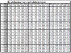
List of up to 15 times the substitute cross-sections for wire diameters from 1 mm to 4 mm

Schematic representation of the drawing-in technique


Characterization of the distributed winding
In the case of stator windings that are electronically commutated or fed from an m-phase network, these phase windings are often nested in one another (distributed winding). A characteristic measure for the winding structure is the number of holes q, which indicates how many slots N are available per strand m and pole (given by the number of poles 2p).

q = number of holes
N = number of grooves
2p = number of poles
m = number of phases
In the case of distributed windings, q ≥ 1, and if q is an integer, it is a full-hole winding. One speaks of broken hole winding when q = zq / nq is a fractional rational number. In the case of single-tooth windings, q <1 and therefore always a fractional rational number.

The winding diagram shows the design of the three-strand winding with 30 coil groups in a winding step of 1: 6 of the same width in a star connection. The summary of the star connections is shown as a circle on the yellow contact rail. Each coil needs two grooves. A number of slots of 30 (coil groups) × 2 slots / group = 60 slots is required in order to achieve a continuous, single-layer assignment of the slots. The number of poles is 10.
The resulting number of holes is determined by:

Manufacturing process of concentrated windings for stator coils

The manufacture of stator windings in concentrated form can be done in a variety of ways. The decisive factor which winding process is used initially depends on the design and structure of a stator and on commercial aspects. Most stator designs can also be wound using several different winding processes. The only exception is the stator construction of the internally grooved solid sheet metal cut, which can only be processed with the needle winding technique and in rare cases with the pull-in technique for concentrated windings. Most concentrated windings are designed as two-layer windings. This means that each tooth has a concentrated winding and there are two coil strands in each slot. With single-layer windings, the center tooth of two adjacent tooth coils is not wound. There is always only one strand of a coil in the slots.
- Internally grooved solid sheet metal cuts
The winding process in question for an internally grooved solid sheet metal stator is essentially limited to needle winding technology. The stator mainly consists of a laminated core, two end plates and slot insulation. The particular advantage of this process technology lies in the fact that, with adequate electrical filling factors, the winding machine produces a finished assembly group. If, on the other hand, joining and interconnection operations are necessary when using individual teeth, all interconnection measures for the partial coils of a phase can be carried out by the winding machine in the case of the solid sheet metal cut. The electrical fill factor can be up to 45%. In view of the low cost of completing a functional stator, losses in terms of the electrical fill factor are gladly accepted. In order to be able to use various additional functions in the winding machine, the end plates are often designed so that they can be used e.g. B. offer the possibility to include insulation displacement contacts. In addition, winding space limits and routing channels for the connecting wires of a phase can be integrated.

The material costs are also manageable due to the small number of individual parts. In connection with the low production costs, the solid sheet metal cutting stator is an alternative suitable for everyday use. When it comes to the design of the solid sheet metal cut, three essential basic concepts always come to the fore. When considering the solid sheet metal stator for concentrated windings, a distinction is made into the following main groups.
a) Paper-insulated solid sheet metal cutting stator

The grooves of the stator package are usually provided with an insulating paper or insulating film before the insulating end plates are put on. The insulation material, e.g. B. Nomex or Mylar or Kapton, is pre-folded from an endless strip, separated to the stator length and inserted into the stator. It is important that the insulation strip is always slightly longer than the stator package, in order to be able to guarantee complete insulation of the winding space from the wire in connection with the length tolerances of the stator package and the insulation paper. The advantage of this design is the small amount of space required by the insulation in the slot area. Here you can achieve insulation thicknesses of only 0.1mm with high dielectric strength. Kapton foils can even be inserted into the package with a material thickness of only a few hundredths of a millimeter. This also has a positive effect on the fill factor to be achieved, since more space is available for the winding.
b) End plate insulated solid sheet metal section stator

With this type of stator design, the stator slot does not need to be lined with insulating paper. The plastic end plates are designed in such a way that molded shafts isolate half of the stator slot on each side. It is also advantageous that the costs for the paper and the costs for the production process for introducing an insulating paper are eliminated. Taking into account a certain wall thickness of these molded-on shafts, it is possible to achieve a Z-shaped overlap of the shafts in the area of the stator slot center in order to increase creepage and air distances to avoid electrical breakdowns. However, it is disadvantageous that, depending on the stator lengths and the plastic material used, the shot depth is limited during the injection molding process. So z. B. when using PA with approx. 25% solids content (e.g. glass fibers) at a depth of approx. 25 mm wall thicknesses of min. 0.5 mm can be achieved. However, this affects in comparison to an insulation paper with a thickness of z. B. only 0.1 mm has a negative effect on the electrical fill factor.
c) molded solid sheet metal stator

The overmolded stator forms an expanded form of the end insulation placed on the stators with molded-on slot shafts. Injection molding technology, which has become more and more sophisticated in recent years, makes it possible to insert a stator package into the injection molding tool and overmold it. As with the end plates with molded-on grooves, wall thicknesses similar to those achieved are achieved. A particular advantage of this process is the avoidance of the pre-assembly of end caps and insulation paper and the risk of insulation gaps that can lead to voltage short circuits. With regard to the high costs for the complex injection molding tool, it is understandable that the costs of individual part insulation are only covered from a lot size of approx. 50,000 stators per year. In addition, it should be noted that a variety of types is only profitable to a limited extent, since the injection molding tool has to be remade when the package length is changed or, of course, when the sheet metal section is changed.
- Grooved solid sheet metal cuts on the outside

Solid sheet metal cuts with grooves on the outside can be processed with needle winding technology, flyer winding technology and linear winding technology. The selected method depends on the number of turns to be achieved and the required fill factors. Flyer winding is particularly useful when a thin wire and a high number of turns are to be expected in connection with a medium-voltage or high-voltage application. Typical applications are therefore in the area of "white goods", such as B. household appliances, or in general building services with an operating voltage of 230 V. In the case of stators with fewer turns, which additionally have only a small mass, it is quite common to process externally grooved solid sheet stators with the needle winding technique or the linear winding technique.

Linear winding application for winding an externally grooved solid sheet metal stator

Needle winding application for winding an externally grooved solid sheet metal cutting stator


Basically, there is just as much variety of insulation forms for externally grooved solid sheet metal cutting stators as for internally grooved stators:

- Segmented stator coils

Segmented stator coils are used, among other things, when a high number of turns is required in addition to the requirements of the high fill factor and the associated orthocyclic winding. They can preferably be processed with the flyer winding technology as well as with the linear winding technology. Due to the freely accessible winding space, it is particularly advantageous with this stator construction to produce windings with precise positions and extremely high fill factors. The design of the segmented stator coils is, however, at the expense of material and production equipment costs. There are often complex procedures to use to shape the individual teeth into a round stator. Another disadvantage, apart from using the pole chain winding technology, is the large number of contact points.
With the segmented stator coils, a distinction is made between T-segments and plugged-in motor coils. Depending on the application, the inserted motor coils can be wound without a body or on a bobbin and then transferred to a T-segment or directly to a solid sheet metal stator. There are three different manufacturing options for the T-segments, depending on the contact points to be expected. On the one hand there is the classic single T-segment, with the disadvantage of the high number of contact points, on the other hand the phase-wound T-segments with a reduced number of contact points and, finally, the winding of so-called pole chains with a greatly reduced number of contact points.
a) T-segments

T-segments are preferably processed with the help of linear winding technology or flyer winding technology. The winding receptacles are designed so that a recording can be carried out on the back of the tooth. In particular, the outer geometry, which later forms the contact surface of the neighboring tooth in the rounded state, is used to fix the tooth in the winding device. However, it is also not unusual to provide a dovetail-shaped groove running axially to the tooth in the outer region of the tooth back, which is useful for fixing the tooth in the winding device. In the same way as with the internally or externally grooved solid sheet metal cuts, the T-segment can optionally be paper-insulated, end-cap-insulated or as an overmolded tooth to insulate the winding.

b) T-segments wound in phases

In connection with a serial connection, T-segments are often produced as a compound of a phase in the form of a tooth chain. The linear winding technology as well as the flyer winding technology are used here as well as with the individual T-segments. When the teeth are wrapped, the end wire of the first tooth is led without interruption to the next tooth, which thus forms the start wire of the second tooth. This procedure continues depending on the number of sub-segments of a phase. There is no significant difference in the design of the components compared to the classic individual teeth. The main reason for processing T-segments in an inverted tooth chain is to reduce the number of contact points. If six contact points are required for three wound individual tooth poles, only two contact points are required with this type of arrangement in the winding machine. This type of production is particularly advantageous for high-current applications with a low operating voltage, since contact resistances and the possibility of errors in the contact points are reduced. The disadvantage, however, is the great effort involved in shaping these inverted tooth chains into a complete stator. For example, it must be ensured that the end wires of each tooth have to be provided with a strain relief so that the winding does not open during handling. This is usually done by attaching an adhesive tape or by a post or pocket-shaped expression of the frontal insulation of the tooth, to which the wire can be fixed after the winding process. If, on the other hand, individual teeth are easy to handle, inverted tooth chains must always be installed carefully, taking into account the risk of damage to the connecting wires.
c) Inserted tooth coils

Plug-in tooth coils are often used in a star-shaped stator design in which a locking ring or yoke is fitted after the coils have been fitted. Solid sheet metal cuts grooved on the inside can also be provided with inserted tooth coils, however, due to the fact that the insertion direction is from the inside to the outside, there is a loss of fill factor. Conical windings are only possible and advantageous if the plug-in direction is directed from the outside to the inside. With the type of insulation, as with the classic single teeth, it is possible to work with paper insulation or end plate insulation. If an overmold is used in a star package, the necessary direct winding with a needle winding system, the flyer winding technology or the linear winding technology means that there are no longer inserted tooth coils.
Inserted tooth coils, like the individual teeth, ultimately require at least two contact points per coil. Inverted tooth chains of a phase interconnected in series are only rarely produced, since, compared to the already difficult assembly of T-segments wound in phases, additional assembly movements (sliding onto the stator package) are added and the length ratios of the connecting wires between the partial coils of a phase change. For this reason, two insulation displacement contacts per coil are often used with inserted tooth coils, which ultimately reach into a control board or a lead frame element via pin-shaped embossings of the contacts .

d) pole chains
With this type of stator design, an attempt is made to combine the advantages of the needle-wound solid sheet metal cut => minimum number of contact points, with the advantages of the linearly wound single tooth => maximum fill factor. Pole chain winding is used for this purpose, which ensures a very high fill factor because the structure of the stator is unfolded into a linear arrangement of the individual teeth and, in contrast to the otherwise common individual teeth, only creates a few contact points. The connecting wires of the partial coils of a phase connected in series do not need to be separated.

For the winding of inverted tooth chains, the flyer winding technology as well as a type of needle winding, the chain winding technology, can be used.

The disadvantage of using the flyer winding technique is that often only one tooth can be wound. Inverted tooth chains are created, but due to the interconnection topology of most stators, they have to be separated again. A simultaneous winding of several phases of a stator is usually not possible.

If, however, with the flyer winding technology for inverted tooth chains, either auxiliary tools are required for depositing the wire in the winding area, or the linear arrangement has to be abandoned at the time of winding an individual tooth, the wire can be deposited directly with the help of the needle winding technology. A particular advantage of using needle winding technology is that, depending on the type of connection of the stator, it is possible to wind all three phases at the same time. The behavior of the connecting wires between the coils of the individual phases when rounding the teeth is particularly advantageous if the linear arrangement of the teeth does not have to be abandoned for winding. So it is useful that the position of the connecting wires runs through the center of the radius of curvature.

This clever arrangement of the wires makes it possible to avoid changes in wire length during the round. When using the needle winding technique, it is quite common to wind several inverted tooth chains at the same time. This is mainly done on carrier tools or workpiece carriers that are positioned in the needle winding machine. Due to the fact that phases U, V and W as well as several stators can be wound at the same time, needle winding technology has a high power density in connection with the use of inverted tooth chains.
Definition of fill factors for motor coils
Motors have to be compact and light, and with less copper they should deliver higher performance. The prerequisite is the appropriate design of the coil formers and wire dimensions. One parameter for the engine developer is the electrical fill factor. The fill factor is a measure of the ratio between the volume of a winding package and the volume required for this to accommodate the winding package. In the case of stators, it can be said that the electrical fill factor is the ratio of the non-ferrous portion of the stator including the stator slot to the sum of the non-insulated copper cross-sections. In contrast to round coils, only the stator slot is considered. The reason for this is that only the conductor strands in the stator slot contribute to the torque of the motor. The winding overhangs on the narrow sides of the winding cross-section of a tooth only result in unwanted losses in the form of an increase in electrical resistance and unwanted heat generation.
Consideration of the winding space of concentrated windings in solid sheet metal cutting stators
As with the round coils, the space requirements of a stator winding are designed using an iterative procedure. First of all, the parameters of the required number of turns, the required wire cross-section and the maximum available space of an insulated stator slot are considered for the calculation basis.
Example calculation of the fill factor of a solid sheet metal cutting stator
An orthocyclic winding design for a stator with 40 turns per tooth and a wire diameter of 0.5 mm is to be calculated. The available insulated changing room is geometrically defined and has an area of 35 mm². An insulating paper with a thickness of 0.25 mm is used.
- Determination of the mechanical fill factor
Given:
Wire Ø Cu 0.5 mm → CU1L = 0.548 mm (table value)
40 turns, insulated winding space area = 35 mm², insulating paper 0.25 mm

When considering the insulated winding space and the required number of turns for a given wire diameter, it can be determined that, taking into account the space required for the winding nozzle (required slot width: approx. ), Only 38 turns can be made in the winding space of the stator slot.


A = sum of the partial areas of the insulated wire
D L = wire diameter over lacquer
n = number of turns per tooth


- Determination of the electrical fill factor
The theoretical consideration is based on the assumption that the non-insulated wire is in the non-insulated groove.
Given: wire Ø Cu 0.5 mm
38 turns, uninsulated winding space area = 41mm²

A = sum of the partial areas of the uninsulated wire
D Cu = bare wire diameter
n = number of turns per tooth


literature
- Eberhard Kallenbach et al .: Electromagnets - Fundamentals, calculation, design and application . 3. Edition. Vieweg + Teubner, Wiesbaden 2008, ISBN 978-3-8351-0138-8 ( limited preview in the Google book search).
- Andreas Dobroschke: winding technology. In: Klaus Feldmann, Volker Schöppner, Günter Spur: Manual joining, handling, assembling. Hanser, Munich, 2014.
- Jürgen Hagedorn, Florian Sell-Le Blanc, Jürgen Fleischer: Manual of winding technology for highly efficient coils and motors, 1st edition, Springer Vieweg, Berlin / Heidelberg 2016, ISBN 978-3662492093