
System separation point
In electrical railway operations, the system separation point is the transition between two power systems. This crossing can be located on an open route, but then only multi-system locomotives can be used, or in a train station (system changing station) .
Different versions of separation points
Non-switchable separation point in the train station

In the case of non-switchable isolating points, a power system is limited to the respective station side. The overhead contact line is separated by a neutral section approximately in the middle across all continuous tracks. The locomotive rolls from one system with a lowered pantograph under the catenary of the other system. Single-system locomotives then either have to be withdrawn from a shunting locomotive independent of contact wire voltage or from the new locomotive from the wagon train and pushed back under their own power system; multi-system locomotives are switched while stationary and then ironed on again. This mode of operation is typical at Italian and Slovenian border stations.
Reversible station tracks
With this variant of the separation point, there are switchable contact line sections in system change stations. If single-system traction vehicles are to be used, the routes for maneuvering must also be switched over. The routes, each with a different contact line voltage, are usually cordoned off by adjustable contact line signals. Passing multi-system vehicles iron after the entrance, during the traffic stop the contact line and at the same time the engine is switched by the driver. After ironing on, the new system continues. Examples include the border station Aachen central station with the system change of 15 kV, 16.7 Hz to Belgian DC system with a voltage of 3 kV, the station Ebenfurth for trains between the network of the OBB and the 25 kV, 50 Hz electrified Raaberbahn and numerous dividing points in the city of London between the busbar system in the south and the 25 kV electrified lines in the north. A clearly visible example is Farringdon station on the Thameslink route. In the Pontresina station of the Rhaetian Railway , platform track 3 has been switchable between 1200 V DC and 11 kV AC voltage since 1981 , especially for the trains of the Bernina Express passing through .

Manual switchover of the contact wire voltage from German 15 kV, 16.7 Hz alternating voltage to Belgian 3 kV direct voltage by the driver of the Thalys multi-system train THA9448 (Cologne – Paris) on track 6 in Aachen main station .
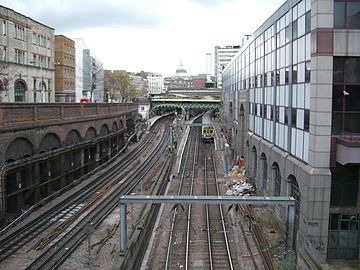
Separation point for the transition between overhead contact line and track at Farringdon station on the Thameslink line in London


Cutting point on the open road
In addition, the system can be changed while a train is in motion at system separation points on the open line. This version is the rule with newer system separation points. If the use of multi-system vehicles is not possible in exceptional cases, contact wire-independent leader or two re-tensioning is required. In contrast to protective sections between different feed areas of the same traction current system , between which a neutral contact wire section is sufficient for separation, system separation points require the interconnection of an earthed section when the contact wire runs through in order to prevent accidental entry by a single-system traction vehicle with a pantograph. The sequence of the sections is live (power system A) - neutral - earthed - neutral - live (power system B). In addition, especially at system separation points between DC and AC voltage systems, the return current is separated by double locking joints (two insulating joints in a row per rail ). At system separation points where catenary networks with different contact wire lateral deflections border one another, the pantographs usually have to be changed because of the different pallet widths. It is also necessary to change the current collector for reasons of wear and tear if different contact strip materials are used in both networks.
In the case of system separation points with different power supply, both supply types are laid overlapping.

System change in Wörth, Karlsruhe light rail network from 15 kV, 16.7 Hz alternating to 750 V direct voltage, page 15 kV

Double section isolators when the system is changed in Wörth, 15 kV on the right, neutral between the isolators, earthed on the left.

Side 750 V with two tram line separators each, the neutral section is between the separators and the grounded section behind.

Tram line separator, the mast switches can be used to supply the neutral and the earthed section with DC voltage if a train comes to a standstill in the system separation point.
A Saarbahn train coming from the 750 V direct current network enters the system separation point in Brebach. The separation point is on the open road, it is driven through with an iron.

Separation point in Bad Wildbad

double barrier joints, Chemnitz Hbf, at the same time the transition between rail and tram operations


Marking of separation points

To ensure that the main switch is switched off and ironed, if necessary, before driving through a separation point, contact line signals are set up at separation points , supplemented by current type and voltage information on a case-by-case basis.
The catenary is also installed and regulated at separation points that are ironed on, so that continuous pantograph operation is still guaranteed. This avoids additional mechanical damage to the vehicle and contact line systems if a driver inadvertently fails to iron.