Contact line signal

An overhead contact line signal is a railway signal that applies to rail vehicles, but also to trolleybuses that are powered by overhead contact lines or power rails .
Installation sites are places where the driver has to turn off the main switch of the locomotive or is allowed to turn it on again, e.g. B. for protective lines , grounded overhead contact line sections under low bridges, or system separation points where the traction current system changes. Switching off avoids damage from tear- off sparks . These sections are to be traversed with momentum.
Other locations are places where the driver has to lower the pantograph or is allowed to put it back on, e.g. B. with interrupted, damaged, lowered or grounded contact lines. Ironing prevents mechanical damage to the contact line and pantograph; the sections without voltage or catenary must be driven through with momentum. Some system separation points must also be ironed through. This applies in particular to those where the pantograph has to be changed due to the deviating clearance profile or the material of the contact strips or where it is to be expected that traction vehicles will run with two pantographs and thus trigger an earth fault.
Finally, contact line signals identify points at which the contact line ends and which a vehicle with a pantograph must not drive over in order to avoid damage.
Country-specific
Germany
The German railway signaling order provides for catenary signals on the top of blue square boards with white signal signs, which are bordered in black and white.
At track junctions, the signals El 1v, El 1, El 3, El 4 and El 6 are supplemented by one or more directional arrows (blue arrow on a white background). The arrow shows which track the signal applies to.
The signals El 1v, El 1, El 2, El 3, El 4 and El 5 are identified by an allocation table if they would also not apply to the neighboring track due to their location between the tracks.
| designation | Signal aspect | meaning | image |
|---|---|---|---|
| El 1v | Two white rectangles lying horizontally next to each other. | Expect signal El 1 (switch-off signal). This signal is basically half the distance of the braking distance of the route in front of the signal El 1. | |
| El 1 - switch-off signal | A disassembled white U. | Turn off the main switch. The main switch must be switched off at the latest at the level of the signal. The signals El 1 and El 2 can be combined at the same location, the signal El 2 is then above the signal El 1. With this combination, shortened protective routes are signaled. In this case, after switching off the signal and driving past, the main switch may be switched on again immediately when the contact line voltage returns. | |
| El 2 - switch-on signal | A closed white U. | Main switch on allowed. | |
| El 3 - "bow down" announcement signal | Two mutually offset white stripes. | Expect signal El 4 (bracket down). This signal is basically half the distance of the braking distance of the route in front of the signal El 4. | |
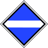
| El 4 - "bow down" signal | A horizontal white stripe. | Strap off (lower pantograph). The signal is located 30 m in front of the section to be traveled with lowered pantographs. The pantograph must be completely lowered at the location of the signal. | |
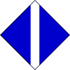
| El 5 - "bracket on" signal | A vertical white stripe. | Bracket on (lift pantograph). The signal is located 30 m behind the section to be traveled with lowered pantographs. The pantograph may be put back on after the signal has passed. | |
| El 6 | A tipped white frame with an tipped white square. | Stop for vehicles with raised pantographs. Vehicles with raised pantographs are prohibited from driving beyond the signal. | |
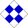
| El 7 - switching signal | A blue and white checkerboard pattern with squares on top. | Interrupt traction current. This signal was only used on the Berlin S-Bahn in the railway network, was used to save energy and is no longer installed. | |
| System change DC voltage | Two horizontal white stripes | This signal stands in the area of system changes, here for the DC start. It is not an independent contact line signal, but is used in conjunction with El 2 or El 5. It is then placed under these signals. The locomotive may only be switched on again (El 2) or the pantographs raised (El 5) once the system has been changed. | |
| System change alternating voltage | A white sine wave and a white number. | This signal stands in the area of system changes, here for the beginning of the alternating current. The white number stands for the respective voltage, in this case 15 kV. It is not an independent contact line signal, but is used in conjunction with El 2 or El 5. It is then placed under these signals. The locomotive may only be switched on again (El 2) or the pantographs raised (El 5) once the system has been changed. |
At system separation points that already existed before the introduction of the system changeover signals, for example in the network of the Karlsruhe Stadtbahn , the contact wire voltages with information on the type of current are marked by white, rectangular boards with black letters.
Austria
The catenary signals in Austria are similar in appearance to the signals set up in Germany. There are blue square signs on the top with white signal signs that are outlined in black and white.
| designation | Signal aspect | meaning | image |
|---|---|---|---|
| "Announcement main switch off" | Two white rectangles next to each other. | Expect the signal "main switch off". The signal is usually placed 300 m in front of the "main switch off" signal. | |
| "Main switch off" | A broken white U. | Turn off the main switch. The signal is usually placed 30 m in front of the protective route. | |
| "Mainswitch on" | A white U. | Turn on the main switch. The signal is usually located 30 m behind the protective route. | |
| "Announcement pantograph low" | Two mutually offset white stripes. | Expect the "pantograph low" signal. The signal is usually placed 300 m in front of the "pantograph low" signal. | |
| "Pantograph deep" | A horizontal white stripe. | Lower pantograph. The signal is usually placed 30 m in front of the track section to be driven on with lowered pantographs. | |
| "Pantograph high" | A vertical white stripe. | Raise pantograph. The signal is usually placed 30 m behind the track section to be driven on with lowered pantographs. | |
| "Stop for vehicles with raised pantographs" | An inverted white square in a white square frame. | The signal marks the point from which journeys for vehicles with raised pantographs are prohibited. |
Switzerland
In Switzerland, contact line signals are yellow / black rectangles (with lowering signals on the top), or light signals that e.g. B. in switchable zones at border stations show the attached power system.
| designation | Signal aspect | meaning | image |
|---|---|---|---|
| Advance signal to the switch-off signal | Two black vertical rectangles or two vertical yellow glowing stripes as a light signal. | Preparing to turn off. A switch-off signal follows. | |
| Switch-off signal | An interrupted black U or a glowing yellow interrupted U as a light signal. | Driving past with the main switch turned off. A switch-on signal follows. | |
| Switch-on signal | A closed black U or a glowing yellow closed U as a light signal. | Continue driving with the main switch switched on. | |
| Advance signal to the lowering signal | Two black squares on top. | The pantographs must be lowered from the lowering signal. | |
| Lowering signal | A horizontal black stripe. | Lower pantograph. | |
| End signal for lowering signal | A vertical black stripe. | Permission to lift the pantograph. | |
| Cancellation signal for lowering signal | A black arrow pointing upwards. | From this point on, the section to be driven on with the pantograph lowered is not driven on. | |
| Signal for route separation | A rectangular vertical board. | Stop for vehicles with raised pantographs when the overhead contact line is switched off. | |
| Switching signal | A horizontal black stripe, above and below a black number. | Stop for single-system and multi-system traction vehicles with raised pantographs. Exception: Motor vehicles with raised pantographs and main switch switched off are allowed to pass, provided that the pantographs can be used for both systems. The upper number relates to the overhead contact line voltage, the lower one to the contact line voltage after the protective section. | |
| End signal to the system protection section | A vertical black stripe with a black number underneath. | Continue with the relevant power system. | |
| Zone protection route signal | An orange lamp. | Stop for single-system and multi-system traction vehicles with raised pantographs. Exception: Motor vehicles with raised pantographs and main switch switched off are allowed to pass, provided that the pantographs can be used for both systems. | |
| Zone signal | An orange number. | The signal shows the switching status of the switchable zone in kV. |
Spain
The Spanish contact line signals correspond in appearance and meaning to the German El 1v and El 1 to 5. The signal corresponding to El 6, which marks the end of contact lines, consists of a square on the top, which is separated by a horizontal and a vertical dividing line is divided into two opposite white and blue triangles.
Web links
- Contact line signals , stellwerke.de
- Contact line signals , lokifahrer.ch


