
Ks signal system

The Ks signaling system (Ks represents K ombinations s ignal) at the 1994 Deutsche Bahn AG (formerly German Federal Railroads and German National Railroad ) is used. There are signals used that pre- and / or main signal function unite in a signal screen. They are gradually replacing the old H / V light and shape signals , the Hl signals and the Sv signals in the context of new signal boxes . Their area of application is limited to electronic interlockings (ESTW) , since the development of corresponding relay assemblies was not considered economical.
history
In the course of German reunification and the associated merger of the Deutsche Bundesbahn with the Deutsche Reichsbahn , the need arose to standardize the different signaling systems in East and West.
The H / V signal system used by the Bundesbahn and the Hl signal system used by the Deutsche Reichsbahn were not compatible with each other, so that it was technically difficult to switch all signals in one part of Germany in a timely manner.
In 1987, the Deutsche Bundesbahn founded a working group to make better use of the expanded possibilities of the newly built electronic interlockings (ESTW) . The Ks signal system was therefore only intended for use with ESTW from the start . Backporting to relay interlockings was not considered. The working group developed its proposal on the basis of the innovative SK signal system that was tried and tested on the Augsburg – Donauwörth route .
The boards of directors of both German state railways decided in March 1991 to introduce this new signal system. It was called the Ks signal system because the primary and primary signals could be combined in one signal. The designation should not be confused with the compact signals (KS), also introduced by the Deutsche Bundesbahn , which represent a new type of signal screen for H / V signals and are optically similar to the Ks signals.
The first line section Magdeburg - Sudenburg - Marienborn equipped with Ks signals was put into operation in 1993 by the Deutsche Reichsbahn within the control area of the Eilsleben electronic interlocking. It was also the first ESTW of the Deutsche Reichsbahn, while the Deutsche Bundesbahn had already put ESTW - but with H / V signals - into operation.
Legally, Ks signals are still not part of the Railway Signal Regulations (ESO). However, they were approved as an operational test with notification ( EBA Pr.2412 Aks521.doc Ms. Rudolph ) for the ESO of the Federal Railway Authority from November 30, 1995 until the 4th amendment regulation to the ESO came into force. However, the aforementioned amending regulation was never issued, so the operational test continues to this day.
With the commissioning of the first route sections with ETCS Level 2 without signals (L2oS), access control signals were introduced for the first time from 2015 . If no path branching exists for a driveway safety signal to a non-equipped L2oS route, this Ks signals can not show the signal phrase "ride" and are in regular train blanked .
construction
The Ks signal system is based on UIC leaflet 732 E (" Principles for signaling train movements with stationary signals "). An essential feature is the separation of train sequence and speed signaling required in the leaflet.


As with the HI signal system, there is only one signal at one location, which is either as
- pure distant signal
- pure home signal or
- combined pre- and main signal (multi-section signal)
can serve.
In contrast to this, with the H / V signal system at the locations of pre- and main signals, both are set up at the same location and electrically interconnected. This allowed the number of light points (without additional lights) to be reduced from seven at H / V (Hp 00, Hp 1, Vr 0 and Vr 1) to three (Hp 0, Ks 1 and Ks 2) for signals without speed restrictions. In addition, space could be saved as only one signal screen is required.
Each signal can receive an additional light, a distinction being made between a shortened braking distance on the preceding or multi-section signal (additional light above) and a distant signal repeater (additional light below). There is no such distinction with H / V. If the signal is equipped with an additional light, this can also be used as a beacon.
In the early days, distant signal repeaters had a large circular circle around the signal lanterns of the main optics. This marking was later abolished, with existing signals initially not being converted.
The main signal optics are solid lenses with a diameter of 136 mm (V 136), while the signal lamps required for other purposes (Zs 1, Zs 7, Sh 1, Ra 12, identification light, additional light) have a diameter of 70 mm (St 70). A white lamp can be used for several purposes (Zs 1, Sh 1, Ra 12), similar to the Hl signal system. With the H / V signal system, multiple use of light points was not possible.
In contrast to the H / V signal system, there is no complicated electrical wiring on the signal. All main optics are controlled individually. This should bring about an increase in reliability and availability. In contrast to the H / V signal system, in which the failure of a lamp could have serious consequences, the Ks signal system is able to compensate for such failures. If, for example, a yellow light of the distant signal fails in the H / V signal system, a main signal at the same location cannot start moving, as the signal aspect Vr 0 of the distant signal must first be ensured. With the Ks signal system, on the other hand, the signal remains on hold if the yellow lamp fails, but changes to Ks 1 (drive) when the following signal starts moving and the yellow signal lamp is therefore no longer required. If, on the other hand, the green lamp has failed, the signal changes to Ks 2 (expect stop), even if the following signal is already moving. With the H / V signal system, the signal remained on hold when the green lamp of the main signal failed. This allows the Ks signaling system to react to lamp failures with minimal operational impact, thereby keeping operations running smoothly.
Special versions of Ks signals are signals that only serve as a target signal for train journeys (only red optics available, so-called “travel image-free” main signals) and signals that are only directed towards dead ends (no green optics available).
Each Ks signal can be configured as operationally switchable. In this case, the upper white light (which can also be used as an additional light) is switched on as an identification light to inform the driver that the signal is not disturbed. A complete blackout is planned in the area of LZB CE 2 . In this case, the red signal lamp is switched off if only one block section reaching up to a block identifier is free in the following section (so-called partial block mode ). With ETCS Level 2, on the other hand, all signals are completely blacked out, so that a train traveling in ETCS Level 2 only passes dark signal screens. The display of green or yellow lanterns, which is still common in LZB CE 2, has been abolished, provided they do not contradict the reference variables.
Speeds are only indicated by speed indicators (Zs 3, Zs 3v). As with the HI signal system, there is the possibility of high signaling .
In some cases, multi-color optics are used on Ks signals, in which up to three colors can be shown at a light exit point instead of one and thus the signal screens can be reduced (from 64 × 125 cm to 50 × 97 cm), since for Hp 0, Ks 1 and Ks 2 only a common optic is required. The light is guided by an LED multi-color signal generator to the light wave exit point via fiber optic cables.
Signal aspects
Depending on the function of the Ks signal, the signal screens have a different appearance:
- Ks distant signal
- Pure Ks pre-signals have two signal lamps, usually arranged horizontally next to each other, in the colors green and yellow. In contrast to the pure Hl pre-signals, the arrangement is mostly opposite: With the Ks signal system, the green lantern is on the left and the yellow lantern on the right .: The signal Ne 2 - pre-signal board is attached to the signal mast (in the first ESTW areas of the Germans Reichsbahn used a yellow triangle pointing downwards with the tip).
- Ks main signal
- Pure Ks main signals have two signal lamps, usually arranged vertically one above the other, with the colors red and green. In contrast to the H / V signal system, the red lantern is usually arranged above and the green lantern below: A white-red-white mast sign (or rarely deviating mast signs for main signals) is attached to the signal mast. In the ESTW pilot projects of the Deutsche Reichsbahn, it was originally a mast sign with a red triangle pointing upwards on a white background.
- Ks multi-section signal
- Ks multi-section signals are main signals that also have a distant signal function. They usually have signal lamps arranged in a triangle, with red at the top in the middle, green on the left and yellow on the right horizontally next to each other under the red signal lamp. In the case of entry signals for a dead end, the green signal lamp may be missing and the yellow signal lamp - if it is not available as blind optics - can be arranged directly under the red signal lamp instead of the green signal lamp there, as is the case with the main signal. If a white-red-white mast sign is attached to the signal mast, there is a yellow triangle pointing downwards to identify the additional distant signal function. In the ESTW pilot projects of the Deutsche Reichsbahn, the red triangle pointing upwards was arranged above the yellow triangle pointing downwards.
| Signal concept, meaning and description | Signal aspects | ||||
|---|---|---|---|---|---|
| Distant signal | Main signal | Multi-section signal | |||
| With
shortened braking distance |
as
Distant signal repeater |
||||
Signal Hp 0 - "Halt" |
|||||
| A red light. |
.png)
|
.png)
|
|||
Ks 1 - "ride" or "expect ride" |
|||||
| A green light or a green flashing light.
The signal shows a green flashing light when a signal Zs 3v is shown on this signal . The signal shown on a main or multi-segment signal allows the speed permitted in the timetable to be used if no signal Zs 3 - speed indicator is displayed. This can be recognized by the fact that “a Ks signal in its function as the main signal is always identified by a mast sign”. If the signal has neither a mast sign nor a Ne 2 signal - pre-signal board , it is a pre-signal repeater. If it is a signal with distant signal function, the next main signal is set to travel. If it is a signal in front of a junction in which a further main signal follows only in a certain direction, the signal may not announce a further main signal despite the yellow triangle . |
.png)
|
_mit_verk%C3%BCrztem_Bremsweg.png)
|
.png)
|
.png)
|
.png)
|
Ks 2 - "expect stop" |
|||||
| A yellow light.
The signal allows the vehicle to pass and announces a stop at the following main signal, a high blocking signal or protective stop signal Sh 0 (old) or Sh 2 (new) at buffer stops. The yellow lamp always shows steady light, even if a signal Zs 3v lights up on the signal or is permanently set up as a board. If the following signal is at a shortened distance from the distant signal, an additional white light will also shine when it is first announced (top left in the signal screen, bottom if it is a repeater). In this case, a speed indicator Zs 3 may be active. |
.png)
|
_mit_verk%C3%BCrztem_Bremsweg.png)
|
.png)
|
.png)
|
|
Additional signal aspects
.png)
- Identification light,
- Additional light (shortened braking distance),
- Hp 0 stop ,
- Ks 1 trip ,
- Waiting for Ks 2 stop ,
- Zs 7 warning signal ,
- Sh 1 / Ra 12 maneuvering allowed (DV 301) or driving ban lifted (DS 301),
- Zs 1 substitute signal and
- Additional light (distant signal repeater).
Ks signals with a distant signal function can use an additional white light in the upper area to indicate that the braking distance between the distant and main signals has been reduced by more than 5%.
In this case, a speed indicator can also indicate a lower speed in order to ensure sufficient braking distance. This speed signaling can subsequently be omitted if the following signal starts moving. The speed signaling can also be due to a missing or shortened slip path behind the following signal. In this case, too, this does not apply afterwards when the following signal starts moving.
A white additional light in the lower area marks the signal as a distant signal repeater, so the signal aspect of the next main signal was announced beforehand. This additional light only lights up if the signal does not show Ks 1 drive (permanently lit, i.e. without Zs 3v).
Ks signals, which are temporarily switched off, show a white light (identification light ) instead of the signal images otherwise provided .
When used in the station area, a Sh 1 / Ra 12 signal (two white lights rising to the right) can be shown, which allows shunting movements to signal that the vehicle is passing the stop.
Sh 1 light signal (DS 301) / signal Ra 12 - shunting signal (DV 301)
When used at operating points where shunting is carried out, the signal Sh 1 light signal (DS 301) / Ra 12 - shunting route signal (DV 301) (two white lights rising to the right) can be shown. In conjunction with signal Hp 0, the signal indicates that the stopping command for maneuvering is canceled and signals that maneuvering is permitted to drive past the stop signal.
Additional signals
In most of the signal screens for Ks main and multi-section signals, the additional signals substitute signal (Zs 1) or caution signal (Zs 7) can be present. A signal is usually only equipped with one of the two additional signals. The caution signal (Zs 7) is mostly used on entry and intermediate signals, the substitute signal (Zs 1) is mostly used on exit and block signals.
The substitute signal is only used in the Ks signal system in the form of a white flashing light. If the signal can also show Sh 1 (DS 301) or Ra 12 (DV 301), the lower left lamp of this signal image is used, otherwise a separate white lamp, which is usually located in the middle in the lower area.
The warning signal is three yellow lights in the form of a V. It allows you to drive past the Hp 0 signal or the disturbed main light signal without a written order, as the following track section could not be checked for the absence of vehicles. Vehicles can therefore be on the track.
Additional signals can be displayed on additional areas below, to the side or above the actual signal.
Additional signals that are usually displayed above the signal:
- Speed indicator (Zs 3) in the form of a white luminous code number or a fixed board. The shape signal Zs 3 on main signals is a black triangle with a white border and a white code number with the tip up.
Additional signals that are usually displayed under the signal:
- Direction indicator (Zs 2) in the form of a white luminous letter
- Direction indicator (Zs 2v) in the form of a glowing yellow letter
- Speed indicator (Zs 3v) in the form of a yellow luminous code number or a board (form signal). To draw attention to the signal Zs 3v, the green light in the signal screen (Ks 1) flashes.
- Opposing track indicator (Zs 6) in the form of a white glowing strip of light rising from right to left, the ends of which can be bent vertically up and down, or a board (form signal), if only exits to the opposite track are possible (when equipped with Zs 8 the same Optics like signal Zs 8)
- Counter-track replacement signal (Zs 8) in the form of a white flashing light strip rising from right to left, the ends of which can be bent vertically up and down (same optics as signal Zs 6)
- Dead-end and early-stop indicator (Zs 13) in the form of an illuminated yellow "T" turned 90 ° to the left or a fixed board
Additional signals that can be displayed next to the signal:
- Counter-track indicator (Zs 6) in the form of a white glowing strip of light rising from right to left, the ends of which can be bent vertically up and down.
- Counter-track replacement signal (Zs 8) in the form of a white flashing light strip rising from right to left, the ends of which can be bent vertically up and down (same optics as signal Zs 6).
Signaling up
At high signaling is the ability to switch a drive concept with a lower speed limit in a drive concept with a higher permissible speed of which use is made mainly on congested road sections, where the signals at very short intervals are consecutive. This possibility already existed with the Hl signals, but not with the H / V signal system, in which a trip concept could not be changed once it had been set.
Graduated down signaling

If there is a stand-alone signal Zs 3 - speed indicator between two main signals, this can also be announced by a signal Zs 3v - speed indicator on the previous main signal.
In this case, the speed limit announced with the aid of the speed indicator does not relate to a speed limit to be expected on the following main signal, but is a stepped down signaling, usually on the way to a stop showing target signal, which in addition to a main signal also z. B. can be a buffer stop. Therefore, the signaling on the previous main signal then takes place with Ks 2 in conjunction with a Zs 3v. (In the case of a speed indicator on a multi-section signal showing "Drive, expect travel", the driver cannot clearly see whether the indicator refers to a speed indicator on the following main signal or a speed indicator upstream of it. In this case, clear signaling is no longer guaranteed.)
Such constellations exist, for example, on all buffer stop tracks in Frankfurt am Main Hauptbahnhof , in Frankfurt (Main) Airport long-distance train station from the direction of Frankfurter-Kreuz-Tunnel or in Heidelberg Hauptbahnhof from all directions.
Upward signaling, which is possible in the same way, is similar in principle, but does not require a speed indicator.
Such signaling is also possible in the H / V signal system.
photos

Multi-section signal with two additional indicators in Dresden-Neustadt station
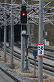
Ks signal in Kinding station (Altmühltal) in the function of a main signal . Signal aspect: Halt (Hp 0)

Signals Hp 0 (stop) at the signal bridge (for the left track) and Ks 1 with Zs 3 Expect travel at 120 km / h and travel (for the right track), both in pre- and main signal function in Dresden- Klotzsche , intermediate signals of the route direction Goerlitz

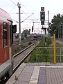
Ks signal ( multi-section signal ) in Ingolstadt Nord in the function of a main and distant signal . Signal aspect: Drive at 80 km / h, expect a stop (Ks 2 with Zs 3) in the shortened braking distance.

Signal Ks 2 (expect stop) on pure distant signal with Ne 2 and fixed Zs 3v (only valid in connection with Ks 1) on the route from Bad Schandau in front of the Neukirch (Lausitz) West train station

Ks signal with Ks 1 at the northern exit on platform 3 of the Lutherstadt Wittenberg train station
Ks signal in Pratau train station with a signal pattern for travel at 80 km / h (Ks 1 with Zs 3)

Ks signal in Hamburg-Ohlsdorf with the signal image driving towards P Poppenbüttel

Ks signal as an entry signal ( multi-section signal ) in the Meckesheim station shows the signal aspect Ks 2 ( expect stop ) in connection with Zs 3v (speed indicator) code number 2 (expect 20 km / h)

Ks main signal with distant signal function ( multi-section signal) as exit signal for Heidelberg Hbf station shows the signal aspect Ks 1 ( expect journey / journey ). The next main signal is about 1400 m away in the Königstuhl tunnel.

Two Ks signals in Viernheim station in a different design than usual for the DB

Ks signal of a design optimized for tunnels in Leipzig Hbf train station (low)
Special version of the multi-section signal in the main train station in Frankfurt am Main

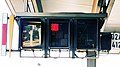
A multi-section signal in Weinheim Central Station . The screen is darkened except for the additional signal. The signal serves in this case as a repeater of the multi-section signal located on the platform.


,_Zwsig_Q102.jpg)


literature
- Reinhold Heissmann, Alfred Slama: The Ks signals and their application. In: signal + wire. 84, No. 9/1992, pp. 246-252.
Web links
- Ks signals on stellwerke.de
- Locations of Ks multi-section signals , main signals and pre-signals (incomplete, based on OpenStreetMap data)
Individual evidence
- ↑ Compilation of the provisions of the Railway Signaling Regulations 1959 (ESO 1959), including the signals approved according to ESO (4) with temporary validity and the instructions issued according to ESO (5) for the implementation of the ESO, valid for the Federal Railways Network (EdB ). ( online )
- ↑ What actually works ... a signal with multi-color optics . In: DB World . No. 6 , June 2017, p. 15 .
- ↑ patent DE202006014793
- ↑ DB Netz AG, Ril 301 - Signal book, announcement 6

Signal systems : H / V signal system (Hp, Vr) Hl signal system (Hl) Ks signal system (Ks) Sv signal system (Sv) Sk signal system (Sk)
Signal types: Level crossing signal (Bü) · Contact line signal (El) · Vehicle signal (Fz) · Main signal (Hp) · Slow speed signal ( Lf) · Secondary signal ( Ne) · Shunting signal (Ra) · Rottenwarnsignal (Ro) · Protection signal (Sh) · Signals for push locomotives and blocking trips (Ts) Advance signal (Vr) Turnout signal (Wn) Train staff signal (Zp) Train signal (Zg) Additional signal (Zs)
Main signals : Einfahrsignal · intermediate signal · Ausfahrsignal · block signal · cover signal