
Substitute signal

|

|
|
|
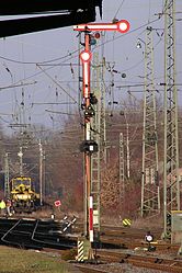
Substitute signal in the H / V signal system (left) and Ks- / Hl signal system (right)
|
||
The substitute signal (Zs 1) is a railway signal from the group of additional signals and is located on main signals .
According to the signal book, it orders : " Drive past the Hp 0 signal or the disturbed main light signal without a written command."
The signal applies to shape signals which show stop (Hp 0) and all main light signals which either show Hp 0 or are disturbed. A fault is understood to mean both a completely dark signal and a dubious or invalid signal image, such as the lighting of several contradicting signal lamps. Such malfunctions can occur if the signal is to come into the driving position, but this does not happen completely due to an error. This can result in contradicting signal patterns that do not exist in the set of rules.
Signal aspect
The signal aspect is available in two variants.
- " Three white lights in the form of an A ": It is the older of the two variants and is only used in the area of the former Deutsche Bundesbahn for shape and light signals of the H / V and Sv signal systems.
- " A white flashing light ": In 1958 a new form was introduced in the signal book of the Deutsche Reichsbahn . Here the signal image is a white flashing light, which is usually arranged below the main red lantern. It was introduced along with the new HI signaling system. In Ks signaling system only this variant is used. In the case of signals that can also show the signal image Sh 1 or Ra 12, one of the two lanterns is also used for the substitute signal. This saved light points.
history
The term substitute signal comes from the fact that before it was introduced to drive past a signal indicating a stop or a disturbed signal, it was always necessary to issue a written command , which should now be replaced by this signal . Issuing an order takes a lot of time. Before the introduction of the train radio , the train driver (not the train driver ) had to report to an entry or block signal on the signal telephone , especially in the event of an unscheduled stop , then received the written order dictated by the dispatcher and then handed a copy to the train crew. For this purpose, command forms were laid out in the signal telephone cabinets. The train radio has simplified the transmission of commands, but it is still only permitted when stationary. If the train radio is disturbed, a messenger may have to bring the order to the train. For these reasons, a possibility was sought to keep operations flowing despite disruptions.
The substitute signal was used for the first time when setting up light day signals on the Lichterfeld suburban railway in 1926 and on a large scale during the electrification of the Berlin city, ring and suburban railways from 1928. With the dense train sequence of around two and a half minutes, the exhibition had an impact The delay of the train concerned also affects the following trains. The signal replaced the written command A, point d, (later point b), which allowed the main signal to pass a stop or be disturbed. The signal image accordingly showed three white lights in the form of an A. The signal was initially included in the preliminary special regulations and was only valid for the Berlin suburban trains. In the new version of the Railway Signal Regulations of April 1, 1935, the replacement signal was introduced across the country as signal Ve 5 in the group of driving prohibition and driving permission signals . The signal designation was later changed to Zs 1.
The Deutsche Reichsbahn introduced the replacement signal with a white flashing light as Zs 1 at the same time as the Hl signals in 1959, the previous signal with three lights was continued as Zs 1a. With the new edition of the signal book in 1971, this variant was given the designation Zs 101 and was thus listed as a discontinued signal that should no longer be set up again. At the same time, the Reichsbahn introduced the manual replacement signal Zs 1 H, with which the command A, point c - entry or continuation from the wrong track - under certain conditions with a hand signal - slow horizontal movement of a green dimmed lamp - could be replaced. The signal was only allowed to be given where it was permitted according to the station book . The hand replacement signal lost its validity in 1992.
With the introduction of the Ks signal system in 1993, the flashing substitute signal was also used there. From November 30, 1995, the validity was extended to the old federal states .
Operational actions
Substitute signals are operated from the interlocking to which the associated main signal also belongs. Only the employee working there can make the necessary backups. The facilities available for securing the driveway are to be used if they can be used. Route levers in mechanical or route signal levers in electromechanical interlockings can be turned into the auxiliary position even in the absence of other requirements and thus lock the switches and side protection devices in the correct position. Exceptions are malfunctions on switches, track closures and blocking signals, provided that these have to be closed for the route. In relay interlockings this corresponds to the locking of the route switches, in this case an auxiliary lock must be set on the route cancellation button (FRT). In the case of routes for which there are no routes, for example when driving from or into the opposite track during construction, the route in the opposite direction should be set as an auxiliary route . If nothing can be used in this form, all the guideway elements must be secured individually, with older interlockings by means of auxiliary barriers, with track plan interlockings by switching off the operator. The automatic turnout must be switched off. These auxiliary measures are not necessary if the route can be set and determined and only no signal travel position takes place. While the activation or release of the substitute signal is possible at any time in mechanical and electromechanical interlockings, some relay and many electronic interlockings check some technical requirements. As a rule, the track section must be reported as occupied before the signal. Since train journeys may only take place under the responsibility of a dispatcher, substitute signals, which are operated from the guard interlocking, are switched depending on the orders. This is the only regular dependency.
When driving on the open route , the responsible dispatcher must introduce feedback (in the case of a non-automatic route block) or obtain an individual evacuation check for the last train that was released. Otherwise, the train to be let down must visually drive the relevant (and possibly the following) section .
If the route is dependent on another interlocking, the route safety and track vacancy detection must (additionally) be guaranteed by a (tele) oral route safety message from the operator of this interlocking. The route safety report must always be given to the dispatcher with a special order before a train journey and entered in the telephone book. The substitute signal is again operated, depending on the technology, either by a single button, by two-button operation or, in the case of electronic interlockings, via the command EE1 or EE2 at the start signal, which must be released. Every substitute signal operation is counted and must be proven in the evidence of the counters as protection against improper operation . In the case of electronic interlockings and relay interlockings with a fault and log printer, the printouts must be kept, unless the interlocking has electronic documentation ( documentation ). This is the case with all newer electronic interlockings. In any case, counting is made on the interlocking that immediately triggers the substitute signal setting.
The operational actions for a train journey with a special order must be observed. The lack of compliance with these regulations by the driver was the cause of the Brühl railway accident in 2000.

Existing train control devices remain in effect. When using the train control system PZB 90 , because of the 2000 Hz magnet placed on the main signal, the command button must be pressed until the indicator light "Command 40" appears after the 2000 Hz control. At the time of the influencing, the PZB 90 on the vehicle monitors compliance with a speed of 45 km / h (this includes a 5 km / h tolerance speed).
As an operational auxiliary measure , the operation of the substitute signal represents a reduction in the level of security, since the technical security is not or not completely given. It may only be carried out if it is ensured by operational substitute measures by the dispatcher that no danger can arise. In the railway accident in Berlin-Wannsee in 1993, in the railway accident in Schrozberg in 2003, in the railway accident in Bad Aibling in 2016 and in the railway accident in Meerbusch-Osterath in December 2017, a train was let into a track section on a replacement signal, in which another Train came or waited.
The substitute signal continues to apply if it goes out before the Zugspitze has passed the signal. The background to this operational regulation is that in some interlocking designs the substitute signal automatically goes out after 90 seconds and repeated operation leads to delays which should be avoided with the substitute signal. In addition, multiple operation of the substitute signal for the same train journey complicates the verification of operation. The substitute signal can, depending on the interlocking design , be deleted again with the signal stop (Sh) or stop group button (HaGT) and, if necessary, the signal button, in electronic interlockings by a corresponding HaGT operation on the magnifying glass. Due to the operational control, a train that is already starting cannot be stopped again. In this case, an emergency stop order must be issued in the event of danger .
The substitute signal can also be set up on "virtual" signals ( ETCS stop board , block identifier ).
In operation with ETCS Level 2 in Germany, an active substitute signal is issued a driving permit in full supervision mode (FS, Full Supervision) with a maximum speed of 40 km / h. This also applies if the substitute signal on the ETCS entry signal is active.
use cases
The substitute signal is used when a main signal cannot be operated or does not come into the driving position. Reasons can be:
- Disturbances:
- Signal disturbance: If a lamp or other signal circuit fails, in the case of form signals, additional difficult movement due to lack of lubrication, frost and snow as well as vegetation or a wire break in the control line.
- Route disturbance: The required route cannot be set, it does not reach the locked state, it does not define or the monitoring does not occur.
- Fault in the track vacancy detection: Incorrect occupancy detection ( red illumination ), although there is actually no vehicle in the track vacancy detection section .
- Block disruption in the route block including change of permit, in old systems also in the station block
- Switch faults (in some cases after local security)
- Temporary routes for which no route is available:
- at entry signals on the opposite track, if it is not fully equipped or if there is no route (long equipment standard for signaled wrong-way operation , no longer permissible for new planning)
- in the case of construction stages, if it is ordered by operating and construction instructions (Betra)
For exits to the opposite track, the opposite track replacement signal (Zs 8) is provided, unless there is an opposite track indicator on the signal as a form signal. Then a substitute signal for travel to the opposite track may only be given here in the event of a fault. In the network of the old German Federal Railroad, a combination of Zs 1 in connection with a free-standing counter-track indicator (Zs 6) before the transition to the opposite track is common.
Except in rare old systems, a main signal is not equipped with a substitute and a caution signal (Zs 7) at the same time .
Planning guidelines

The substitute signal may be provided on all main signals in the new building. However, it may only be planned as an alternative to a caution signal. Whether a substitute signal or a caution signal is used must be agreed with the company as part of the operational task definition (BAST). As a rule, it is used on exit and block signals, while caution signals are used on entry and intermediate signals from remote-controlled and therefore unoccupied stations. Since light points are already provided for the substitute signal in the usual main signal screens and the costs for laying the cables depend primarily on the underground construction (and only to a small extent on the number of wires), the installation is hardly associated with additional costs. The symbol in the safety-related site plan is an open tip pointing upwards, which is located above the associated main signal.

Switched on substitute signal at an H / V light main signal
Switched on substitute signal at a form main signal (here: as opposite track substitute signal)

Substitute signal on a HI signal screen


See also
- Auxiliary signal (Switzerland)
Web links
Individual evidence
- ↑ Deutsche Bahn AG: Guideline (Ril) 301, Module 301.0301, Section 2, Paragraph 1 as well as in the Railway Signaling Regulations (ESO).
- ^ Deutsche Bahn AG: Ril 301, Module 301.0301, Section 2, Paragraph 2 as well as in the ESO
- ↑ Manuel Jacob: The electrical operation on the Berlin S-Bahn. Volume 7: "Safe is Safe" - How it works on the Berlin S-Bahn . VBN Verlag B. Neddermeyer, Berlin 2000, ISBN 3-933254-05-1 , p. 49-52 .
- ↑ Bernd Kuhlmann: Signal connections. The signal system of the light rail from 1928 . In: Electricity instead of steam! GVE, Berlin 1999, ISBN 3-89218-275-2 , pp. 52-61 .
- ↑ Overview of the essential changes to the 1971 edition of the Signalbuch compared to the 1958 edition . Section 2.4 Changes to Section 3. On § 7 Paragraph 1. S. 11 .
- ↑ Overview of the essential changes to the 1971 edition of the Signalbuch compared to the 1958 edition . Section 2.4 Changes to Section 3. On § 7 paragraphs 8 and 9 . 12 .
- ↑ Overview of the essential changes to the 1971 edition of the Signalbuch compared to the 1958 edition . Section 2.4 Changes to Section 3. On Section 7 (10) p. 12 .
- ↑ Eisenbahn-Bundesamt (Ed.): Eisenbahn-Signalordnung (ESO) with instructions for carrying out the ESO and signals with temporary validity . September 18, 2015, p. 143 ( bund.de [PDF; accessed on March 11, 2018]).
- ↑ Eisenbahn-Bundesamt (Ed.): Eisenbahn-Signalordnung (ESO) with instructions for carrying out the ESO and signals with temporary validity . September 18, 2015, p. 39 ( bund.de [PDF; accessed on March 11, 2018]).
- ↑ The Meerbusch train accident has still not been resolved . WZ.de, August 22, 2018
- ↑ ETCS for hobbyists: Operating modes OS, SR and Override. In: youtube.com. May 27, 2019, accessed June 1, 2019 .
- ↑ Study on the introduction of ETCS in the core network of the Stuttgart S-Bahn. (PDF) Final report. WSP Infrastructure Engineering, NEXTRAIL, quattron management consulting, VIA Consulting & Development GmbH, Railistics, January 30, 2019, p. 85 f. , accessed April 26, 2019 .
- ^ Holger Metschulat: additional signals. In: stellwerke.de. July 19, 2006, accessed March 11, 2018 .
- ↑ Deutsche Bahn AG: Guideline 819 "Planning LST Systems", Module 819.9002 "Symbols for Safety Plans"

Signal systems : H / V signal system (Hp, Vr) Hl signal system (Hl) Ks signal system (Ks) Sv signal system (Sv) Sk signal system (Sk)
Signal types: Level crossing signal (Bü) · Contact line signal (El) · Vehicle signal (Fz) · Main signal (Hp) · Slow speed signal ( Lf) · Secondary signal ( Ne) · Shunting signal (Ra) · Rottenwarnsignal (Ro) · Protection signal (Sh) · Signals for push locomotives and blocking trips (Ts) Advance signal (Vr) Turnout signal (Wn) Train staff signal (Zp) Train signal (Zg) Additional signal (Zs)
Main signals : Einfahrsignal · intermediate signal · Ausfahrsignal · block signal · cover signal