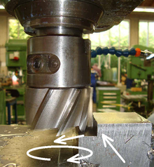
Feed rate

The feed rate is a term from machining technology , a branch of manufacturing technology . With machine tools it indicates the speed of the tool in the feed direction and is usually given in mm / min.
A distinction is made between the rapid traverse process and the feed movement required for machining. In the CNC technique is given to the machine via a specific programming language z. B. DIN-ISO control, Siemens control, Fanuc control or Heidenhain control (plain text) specified travel paths. A distinction is made between point , line and path control (depending on the machine type: X / A, Y / B, Z / C axes, with axes A, B and C, the swivel axes, the main machining axes X, Y and Z belong). The feed movement "G1" (path condition "G" function) can be imagined in a figurative sense like driving a car in a town with a limited or specified speed (v). Figuratively speaking, driving on the motorway at unlimited speed would be the rapid traverse method "G0". This is positioned with a certain safety margin in front of a contour to be machined and / or in front of the "workpiece zero point" of the component or at the so-called "program zero point" after the end of the contour (e.g. tool change). The size of the feed speed is calculated from the distance that the tool ( turning ) or the workpiece ( milling ) travels in the feed direction, depending on the frequency of rotation to be performed, per unit of time.
| Rotation frequency | 1 / min | |
| Feed | mm | |
| Rotation frequency | 1 / min | |
| Feed per cutting edge | mm | |
| Number of cutting edges | - | |
There are many factors that play a role in selecting the feed rate when turning. In this manufacturing process , the main spindle , in which the workpiece is securely clamped with hard or soft jaws ( work safety ), exerts a powerful and powerful rotating movement (depending on the gear stage). The tool ( lathe chisel ) changes its position in space through the "feed movement". With a particular feed depth ( ), and a negative angle of inclination ( roughing ) of the cutting plate or the tool holder and the material adapted cutting material , as well as a properly selected chip cross ( ), resulting in a function of the indexable insert geometry (CNMM120412-PR 4215) a specific cutting force . In addition, the ideal cutting speed (peripheral speed) must be selected for the material to be machined . Due to these geometrically determined cutting tools and the very high surface pressure required between the cutting material and the material, the feed speed will tear off the material in a helix movement due to the tangential contact of the two planes (workpiece and tool), so that machining begins at the moment of contact.
At constant speed, the feed rate is proportional to the rotational frequency n .; With CNC-controlled machine tools you can choose between “constant G97” and “increasing G96” speed. With increasing speed, e.g. B. transverse facing, the frequency of rotation increases the smaller the diameter, and in contrast, this decreases with ever larger diameter. This has the consequence that during roughing / finishing the frequency of rotation is adapted to each different diameter so that the feed rate remains constant for the given surface properties. However, empirical values show that if certain tolerances (clearance, transition or oversize fits) have to be demanded or manufactured, the increasing speed can have negative effects on tight tolerances. The feed rate must also adapt to the changing frequency of rotation. It may be possible that the feed does not keep up with the speed and thus creates a wave-like surface due to an excessively high frequency of rotation (shape and position tolerance not given). It is not just the service life (wear) of a tool cutting edge that depends on the cutting speed. The greater the cutting speed, the more friction the cutting edge has to overcome. The more friction has to be overcome, the more heat is generated. The more heat is generated, the more heat the cutting edge has to absorb and transmit (hot hardness). If the cutting plate is not sufficiently cooled , it will be at the end of the service life of the z. B. indexable insert come so that the required tolerances can no longer be met.
Since it is cumbersome to use in individual machining processes, one usually works with the feed size . It is the path in the feed direction of the workpiece or tool that is covered per revolution or stroke. The feed rate is selected according to the resilience of the cutting edges, the material and, when finishing, the desired surface roughness.
- When turning , the feed rate is specified in millimeters per revolution of the workpiece, as a chip of the same thickness is always formed with different workpiece diameters .
- Since the tools often have many cutting edges working at the same time during milling , the tool feed per minute (mm / min) is calculated here with the tooth feed via the tool revolutions per minute (1 / min).
- The feed rate can vary greatly during grinding . When grinding longitudinally, however, it is important that the feed rate per grinding wheel revolution does not exceed the width of the wheel, otherwise unprocessed areas will remain.
- There is no feed when broaching , because here the feed is integrated into the broach , only the cutting speed is calculated.


