Battery switching system
A battery switchover system is an electrical assembly with which it is possible to supply the starter in vehicles with a higher voltage than the on- board network supplies during normal operation. The system is used in heavy commercial vehicles.
Basics
Heavy commercial vehicles are equipped with diesel engines that have a displacement of up to 24 liters. Such large engines require a starter with an output of up to nine kilowatts for the starting process . Although these vehicles are equipped with a battery that has a capacity of up to 230 ampere-hours , a single 12-volt battery is already reaching its performance limit . Due to the high load torque and the resulting high starting and drag currents, 12-volt starters are not suitable for starting such motors. By doubling the voltage, the current could be halved with the same power . For this purpose, two 12-volt batteries have to be connected in series and you get an on-board voltage of 24 volts. This voltage has the advantage that, particularly in the starting system, voltage losses are not as disadvantageous as with the lower voltage of 12 volts. However, all other electrical components would then also have to be designed for 24 volts. An alternative is a mixed 12/24 volt system. In this system, the starter is designed for 24 volts, but the remaining components are designed for 12 volts. In order to be able to implement this on-board network, a battery switching system is required.
Structure and interconnection
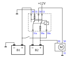
The central switching unit in this system is the battery switchover relay. This is a relay that is equipped with two changeover contacts. The contacts are designed for high switching currents. The relay coil of this relay is designed for 12 volts. A second starter battery is also part of the system. Both batteries must be of the same age and have the same technical data. So that both batteries are loaded equally, the connecting cables must have the same cross-section and be of the same length. The negative pole of one of the batteries (battery 1) is connected directly to ground, the negative pole of the other battery (battery 2) is connected to terminal 31a of the changeover contact of the battery changeover relay and from there connected to ground via terminal 31 . The positive pole of battery 1 is connected to connection 30 of the battery changeover relay. The positive pole of the battery 2 is connected to the connection 30 of the starter. In addition, the positive pole of the battery 2 is connected to the terminal 30 a of the second changeover contact. Terminal 50 of the battery changeover relay is connected to terminal 50 of the starter. Terminal 51 of the battery switchover relay is connected to the on-board network plus. The ignition / start switch is connected to connection 50 a .
function
In the idle state, both batteries are connected in parallel via the battery switchover relay (connection 30 a - 51) . If the ignition / start switch is now actuated, the coil of the battery switchover relay is supplied with voltage and picks up. The contacts now switch and the two batteries are connected in series via the first changeover contact (contact 31 a - 30). The starter now receives 24 volts at terminals 30 and 50 via the second changeover contact (connection 30 a - 50). The starter rotates and starts the engine. The rest of the vehicle electrical system continues to be supplied with 12 volts from battery 1. After the start process has ended and the ignition / start switch has been released, the relay coil is de-energized again. As a result, the battery changeover relay switches the contacts back to the rest position. The two batteries are switched in parallel again. The alternator powered by the combustion engine now supplies both batteries with electricity and they are charged.
Individual evidence
- ^ A b c d e f g h Jürgen Kasedorf, Richard Koch: Service primer for vehicle electrics. 14th revised edition, Vogel Buchverlag, 2001, ISBN 3-8023-1881-1 , pp. 183-185.
- ^ A b c d e f Robert Bosch GmbH (Ed.): Autoelectrics Autoelectronics. 3rd updated edition. Friedrich Vieweg & Sohn Verlagsgesellschaft mbH, Wiesbaden 1998, ISBN 978-3-322-91537-5 , pp. 104-106.
- ↑ a b BOSCH: Technical instruction on electrical starting systems. Robert Bosch GmbH Stuttgart, Automotive Equipment Division, 1972, VDT-UBE 501/1.
- ↑ Erich Hoepke, Stefan Breuer (eds.), Wolfgang Appel, Hermann Brähler, Ulrich Dahlhaus, Thomas Esch, Stephan Kopp, Bernd Rhein: Commercial vehicle technology. Basics - Systems - Components, 6th revised edition, ATZ / MTZ reference book, Vieweg + Teubner Verlag, Wiesbaden 2010, ISBN 978-3-8348-0995-7 , pp. 492–494.
- ↑ Radomir Michal Fabis: Contribution to energy management in vehicle electrical systems. Approved dissertation from the Technical University of Berlin, Berlin 2006, pp. 17–22.
- ^ Rudolf Hüppen, Dieter Korp: Auto electrics all types. Motorbuchverlag, Stuttgart, 1968, ISBN 3-87943-059-4 , pp. 52-53.
- ↑ a b Jens Feddern: Theory and practice of board electrics. 5th revised edition, Delius Klasing Verlag, Bielefeld 2009, ISBN 978-3-7688-0913-9 , pp. 54-57.
- ^ A b c d e f Franz Gretzmeier, Wilfried Staudt (ed.), Siegfried Blüml: Motor vehicle electronics Motor vehicle electronics . Textbook and workbook on automotive system technology, Springer Fachmedien Wiesbaden GmbH, Wiesbaden 1996, ISBN 978-3-663-01983-1 , p. 181.
- ↑ a b c d e Robert Bosch GmbH (Ed.): Autoelectrics Autoelectronics. 4th completely revised and expanded edition. Friedrich Vieweg & Sohn Verlagsgesellschaft mbH, Braunschweig / Wiesbaden 2002, ISBN 978-3-322-91561-0 , pp. 106-107.
Web links
- Circuit example of a battery changeover relay. (accessed on August 18, 2016)
- Technical information terminal designations DIN 72552. (accessed on August 18, 2016)
