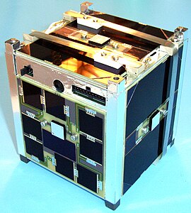
BeeSat
| BeeSat | |
|---|---|

|
|
| Country: |
|
| Operator: | Technical University Berlin |
| COSPAR-ID : | 2009-051C |
| Mission dates | |
| Size: | 10 × 10 × 10 cm |
| Begin: | September 23, 2009, 06:21 UTC |
| Starting place: | Satish Dhawan Space Center |
| Launcher: | PSLV C14 |
| Status: | Project finished |
| Orbit data | |
| Rotation time : | 99.1 min |
| Orbit inclination : | 98.3 ° |
| Apogee height : | 725.9 km |
| Perigee height : | 716.6 km |
BeeSat (also Tubsat 8 ) was a picosatellite project at the Technical University of Berlin . BeeSat fulfills the Cubesat standard and therefore has external dimensions of 10 × 10 × 10 cm³ and a total mass of less than 1 kg. The main objective of the project was the space verification of newly developed, miniaturized reaction wheels and other technologies for pico satellites. In this way, fields of application should be opened up and the special advantages of highly miniaturized satellites made further usable. The successors are Beesat-2 , Beesat-3 and Beesat-4 .
Mission objectives
The primary goal of BeeSat was to develop and test technologies that have long been available for larger satellites for pico satellites. A number of mission scenarios require a functioning attitude control, which is why BeeSat should test a number of miniaturized components in this field.
Among other things, BeeSat flew with newly developed, highly miniaturized reaction wheels, sun sensors based on position sensitive devices and magnetic coils in PCB design . In addition, a number of other Pico satellite technologies such as a new on-board computer (2 redundant ARM-7 based microcontrollers, 60 MHz) and a complex energy board should be tested.
begin
BeeSat was launched into sun-synchronous orbit on September 23, 2009 by an Indian PSLV rocket . After the launch and early orbit phase , in which, as is usual with university satellites , a number of ground stations are requested to track the satellite and report contacts, BeeSat was to carry out its experiments and, among other things, provide services for radio amateurs as a digipeater .
Technical specifications
Energy supply system
The electrical energy to operate the satellite was generated using GaAs triple junction solar cells . At the end of the planned service life, the minimum power generated from sunlight should still be around 1.36 W, while the average power consumption was set at 0.5 W. The energy board recorded 38 housekeeping data in order to document the state of the satellite and to be able to intervene in the event of any deviations from the norm.
Position control system
For attitude control , a sun sensor based on a position sensitive device was attached to each side of the satellite, which was used to determine the relative orientation to the sun. Two three-axis magnetic field sensors were supposed to measure the earth's magnetic field. The orientation of the satellite in space should then be determined from solar and magnetic field measurements using various models (orbit, solar and geomagnetic field models). In addition, three gyros arranged at right angles served as reference instruments . By reaction wheels dan should be made to the predetermined position effect and the satellite can be directed towards its target. 6 magnetic coils were used to desaturate the reaction wheels.
Board computer
The relatively complex calculations of the on-board software (mainly of the position control system) should be carried out with two redundant ARM-7 based microcontrollers with a clock rate of 60 MHz. There was a 16 MB program memory which was designed to load software via telecommand even after the start. The on-board computer should record 48 analog data on the state of the satellite and store it in the 4 Mbyte telemetry memory.
Communication system
The satellite was supposed to transmit with the callsign DP0BEE in the 70 centimeter band around 436 MHz. A transmission power of 0.5 W at a downlink rate that could be switched between 9600 and 4800 bit / s was planned. The uplink should be in half-duplex mode at 4800 bit / s. In addition, radio beacons and digipeaters should be provided for radio amateurs .
camera
The on-board camera should take pictures of the earth's surface and then send them to the ground station for evaluation. It should also serve as an additional means of verifying the position control . A sensor with 640 by 480 pixels was used, in front of which a Bayer mosaic filter sits. The color depth was 8 bits per component, and the images should be compressed with an adjustable degree of compression .
Web links
- Beesat 1 , TU Berlin
Individual evidence
- ↑ orbit data according to BEESAT. n2yo.com, July 8, 2012, accessed July 8, 2012 .
- ↑ BEESAT-2. (No longer available online.) TU Berlin, March 18, 2011, archived from the original on August 18, 2012 ; Retrieved September 3, 2012 .
- ↑ What is BEESAT-3? (No longer available online.) TU Berlin, October 18, 2010, archived from the original on August 18, 2012 ; Retrieved September 3, 2012 .
- ↑ Gunter Krebs: BeeSat 1, 2, 3, 4 (Tubsat 8, 9, 10). In: Gunter's Space Page. June 22, 2016, accessed June 22, 2016 .