Boundary layer separation
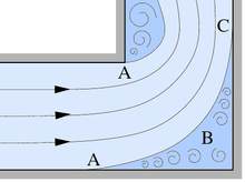
Boundary layer detachment is a fluid mechanical effect which means that a flow does not follow the contour of a body in flow, see figure on the right. Downstream of the separation points (A), a swirling area (light blue), often referred to as dead water or wake , forms between the main laminar flow (blue streamlines ) and the body contour (black) . If the body expands sufficiently, the flow can rest on the body at another point (C). The swirled area (B) between the detachment and reattachment points forms a detachment bubble .
Boundary layer separations are the cause of flow breaks with often undesirable, sometimes dramatic effects. Boundary layer detachment on wings reduces lift, which can lead to aircraft crashes. Boundary layer separation can also occur in jet engines, which can lead to a collapse in propulsion power. Aerodynamically, detachments cause a reverse flow area, which increases the flow resistance, an effect that is mostly undesirable in airplanes, cars and ships, but is welcome in air brakes , parachutes or sea anchors .
Boundary layer separation on wings
If you consider the air flow around a wing profile with increasing angle of attack , it can be seen that the air flow around the profile is initially laminar. At a certain angle of attack, which is not too large, the flow then partially detaches from the profile contour and re-applies after a certain distance. A laminar separation bubble has formed between separation and re- application , because the flow is laminar until it is separated.
In both cases, detachments occur in the area of the pressure increase, so they can be observed behind the thickest point of the profile. At the thickest point the pressure has a minimum and increases again downstream. The opposite is true of the velocity, which has a maximum at the thickest point of the profile, is decelerated downstream by the pressure increase and the flow releases kinetic energy. If the back pressure is high enough, the flow becomes unstable, turbulence and a separation bubble form.
The energy loss in the boundary layer can be seen as the reason for the separation of the flow when sweeping over the profile contour. After a certain running length, the flow is no longer able to follow the profile contour, so that the flow leaves the contour and detaches itself from it. In a turbulent flow, the velocity of the fluid elements is higher near the wall (see figure “ Flow velocities ”), so that they run longer against an increase in pressure and can continue to follow the contour. However, this accumulation of kinetic energy results in an increase in the flow resistance.
The flow around the wing is hindered by the separation of the boundary layers, which is why it has a negative impact on the flight performance of an aircraft. The larger the angle of attack of the profile, the earlier the flow will break away from the top until it can no longer come into contact, see figure " Boundary layer separation ". This so-called stall can lead to the aircraft crashing.
With the help of turbulators it is possible to deliberately make the boundary layer flow turbulent. The exchange of momentum increases due to the turbulence. As a result, the flow becomes more energetic near the wall, it can follow the profile contour more easily and the separation bubble is prevented. However, since the location of the separation bubble depends on the angle of attack, a generally optimal location for the turbulators on the wing surface cannot be clearly determined over the entire range of the angle of attack. On the upper side of the wing it makes no sense to force turbulence on the flow, because due to the geometry of the profile, the area of the detachments on the wing is too large over the entire range of the angle of attack. When using turbulators, a compromise between good flight performance in slow flight and high-speed flight can practically only be achieved by placing them on the underside of the profile. A separation bubble only arises here in high-speed flight, i.e. at low angles of attack.
Fluid mechanics background
In the case of slender bodies that are not inclined too much in relation to the main flow and a sufficiently large Reynolds number, the viscosity of the medium can be neglected in the majority of the flow field. However, the influence of the viscosity near the wall - in the so-called boundary layer - should by no means be neglected . The thickness of this boundary layer is very small when there is a current, but the frictional resistance of the body in flow forms in it, which together with the pressure resistance makes up the flow resistance of a body. The fluid elements adhere directly to the body ( adhesion condition ) and within the boundary layer their speed adapts to that of the main flow. The pressure is approximately constant across the thickness of the boundary layer and is applied by the main flow.
Laminar boundary layer separation
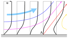
In a fluid (liquid or gas) with low viscosity , in a steady flow in which the potential energy does not play a role, the sum of the kinetic energy and the static pressure , the total pressure , is constant along a streamline. The static pressure is the pressure felt by a fluid element that is moved with the flow. If the static pressure increases near a wall in the direction of flow, the main flow is decelerated and the slower fluid elements near the wall are decelerated even more by the friction. If the delay is large enough, a backflow area occurs (orange in the figure, far right) and the flow separates from the wall. At the separation point A, a streamline (red) leaves the wall at a certain angle. If the Reynolds numbers are not too large, the boundary layer can detach now, which then defines a laminar boundary layer detachment. At this point, however, the flow is unstable and often turns into turbulent flow. The separation point is where the gradient of the velocity u parallel to the wall disappears perpendicular to the wall (in y-direction):
see the thick, black, bottom-up lines that illustrate the horizontal component of velocity. In Newtonian fluids , the wall shear stress is proportional to this velocity gradient and is therefore zero at the separation point.
Turbulent boundary layer separation
With higher Reynolds number turbulent boundary layer, which is thickened by the vortex starts behind the separation point (blue line in Figure Plattenumströmung ). Turbulent flows have higher velocities near the wall due to the bulky flow profile (see figure on the right), which results in a higher momentum of the fluid elements. With this impulse, the fluid elements are able to counter increasing pressure for longer: separation therefore only occurs later than with a laminar boundary layer. The sudden decrease in the drag coefficient of a sphere by an order of magnitude at Re = 4 · 10 5 is explained by the turbulent boundary layer, because because it is longer on the leeward side of the sphere, the turbulent wake at low pressure is narrower, so that the pressure resistance suddenly decreases.
If the pressure increase is sufficiently high, a turbulent boundary layer can no longer follow the contour, which then ultimately leads to a turbulent boundary layer detachment.
Reinvestment of the flow
A boundary layer detachment has its cause in an opposing pressure increase and when this cause disappears, a flow can also build up again. This is the case, for example, with a flow through a knee, see figure on the right: In the outer radius of the flow, the speed decreases and the pressure - according to Bernoulli's pressure equation - increases, which leads to the separation bubble (B). Behind the knee, the speed increases again and the pressure decreases: the current starts again. Detachments similar to those in front of the knee can also form in front of a narrowing of a pipe through which the flow passes. In the narrowed area of the pipe, with constant mass flow, the speed is increased and the static pressure is reduced, so that the flow is applied again there.
Periodic replacements
Periodic vortex shedding as in the Kármán vortex street cause periodic forces with a certain frequency on the structure through equally periodic pressure distributions. If the excitation frequency coincides with a natural frequency of the structure, resonance effects occur that can damage the structure. If the frequency is high enough, such periodic detachments can also generate audible sound.
Sound radiation in the case of periodic detachments can also occur if the instability at the detachment point is triggered by an acoustic sound field triggered by the detachment. This feedback can lead to whistling tones with high sound levels in the event of resonance.
Such sound sources can be avoided by using so-called turbulators .
Influences on and influencing of detachments
The formation of a detachment is particularly of the Reynolds number
dependent, i.e. on the flow velocity , a characteristic length in the flow field (can also be a radius of curvature ), the kinematic viscosity ν , the dynamic viscosity η = ν · ρ and / or the density ρ of the medium. In general, the gradual widening of channels or sufficiently slim, streamlined body contours lying in the direction of flow cause the acceleration of the external flow to outweigh the increase in pressure and the flow to remain adjacent.
There are many adaptations in nature and technology to delay or prevent the flow separation if the above requirements cannot be met. The Alula in birds causes similar slat a late replacement at low speeds. Deflection blades in a wind tunnel are intended to prevent flow separation in an internal flow. Separation bubbles can be sucked off and the impulse of the flow close to the wall can be increased by blowing in, both of which promote the attachment of the boundary layer , see sucking off / blowing out the boundary layer .
Because turbulent boundary layers separate later than laminar boundary layers due to their higher flow velocity near the wall, tennis and golf balls have a skin or dents which, as turbulators, ensure that the flow remains in place for longer, which reduces the pressure resistance so that the balls fly faster and further. Every wall has a laminar sub-layer - even under a turbulent boundary layer. Only when the roughness penetrates this sub-layer does it have an impact on the boundary layer, the frictional resistance and the flow. If, on the other hand, the sub-layer completely covers the roughness, the wall is "hydraulically smooth".
literature
- H. Oertel (ed.): Prandtl guide through fluid mechanics . Fundamentals and phenomena. 13th edition. Springer Vieweg, 2012, ISBN 978-3-8348-1918-5 .
- F. Durst: Fundamentals of Fluid Mechanics . Springer, 2006, ISBN 3-540-31323-0 .
Web links
- Hartmut Siegmann: Profile Light - Upwind. January 24, 2016, accessed January 24, 2016 .
Individual evidence
- ↑ Lexicon of Physics. In: Spektrum.de.
- ↑ Oertel (2012), p. 113 and p. 276
- ↑ Oertel (2012), p. 113
- ↑ Oertel (2012), p. 116


