Artificial horizon
An artificial horizon ( English artificial horizon or gyro horizon , also attitude indicator ) replaces the natural horizon if it is not visible or if the spatial position is to be measured. Above all, artificial horizons are needed
- in aviation (especially for climbing, descending and turning ),
- for chassis or vehicle stabilization,
- when stabilizing cameras, scanners and target devices,
- in the monitoring and control of construction machinery ,
- in active tilting technology for rail vehicles and track measurement,
- when centering GPS and other radio antennas.
Many calculations for determining position , which previously required an artificial horizon, are now being replaced by GNSS satellite surveying. However, the relationship to the earth's gravity and the terrestrial altitude system is lost, which must be taken into account when determining the exact location.
Measurement principles
The instrumental representation of the horizon can either be static or dynamic.
Dynamic measurement
The absolute elevation angle cannot be determined in this way on moving carrier systems such as airplanes, road vehicles, rail vehicles and ships or, for example, swinging structures such as bridges, cranes, etc., since Newton's axioms do not distinguish between the acceleration due to gravity and the centripetal acceleration of the moving carrier can. With moving objects, such devices are subject to the inertial force resulting from the acceleration (which shows up as centrifugal force during circular movements ) and do not show the actual vertical, but the apparent perpendicular . A stable gyro instrument is therefore used in aviation in order to obtain a reference for the true perpendicular and the horizon.
Measurement systems have been developed by industry with which the angle of inclination with respect to the horizon can be precisely determined even on dynamically moving carriers. The angle of inclination is understood to mean the longitudinal inclination ( pitch angle ) and the transverse inclination ( roll angle ). Such a measuring system is also called an artificial horizon. For vehicles with a pronounced preferred direction of movement (motor vehicle, ship, submarine, rail vehicle), an external speed signal can be fed in as support information for precise applications (speedometer, GPS, DGPS , radar, etc.).
The following describes the artificial horizon as it is used in aircraft. Its development goes back to Lawrence Sperry .
Aircraft instrument
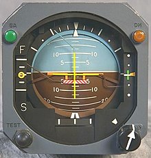
The artificial horizon (Engl. Attitude indicator ), also horizon gyro or officially Adi called, as air traffic control unit used to determine the position of the aircraft to the surface. It offers a direct, pictorial representation of the position in relation to the earth's surface by showing the flight attitude around the longitudinal axis ( roll or bank attitude ) and around the transverse axis ( pitch attitude ). All other instruments in the aircraft can only be used indirectly to determine the flight attitude . Movements around the vertical axis, on the other hand, are not represented by the artificial horizon, but by another gyro - the turning pointer .
The instrument is essential for flight according to instrument flight rules and also for night vision flight . Even in flight according to visual flight rules it can be useful or necessary when the natural horizon reference becomes difficult; for example in hazy weather over open water. On the other hand, the instrument should not induce a pilot to consciously continue the flight in poor visibility.
At least two independently functioning systems are required for instrument flight. In the case of large traffic machines, there is even a third, independent emergency system supplied with its own emergency battery.
There are different ways of generating the reference with which the pilot is shown the position of his aircraft relative to the earth. The simplest possibility is described here, which is also available in the modern cockpit with electronic flight instruments as a backup system: the gyro driven by negative pressure with a vertical axis, which mechanically transfers its movement to the scale image with the horizon line.
construction
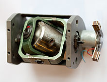
The artificial horizon contains a so-called horizon or plumb top , which remains stable in its position in space due to a high speed (typically 15,000 to 20,000 revolutions per minute) and the effect of the gyroscope , see twist stabilization . The fully cardanic (with three degrees of freedom ) suspended gyro is driven electrically or by means of negative pressure.
The pneumatically driven gyro contains inclined nozzles on its periphery, through which a powerful air stream emerges. The air is supplied via a pipe that runs through the axes of the cardanic suspension so that no torque is generated. The necessary pressure difference can be maintained by a pressure pump on the supply line or a suction pump on the housing; the latter solution is usually used.
The position of the gyro axis in relation to the housing can be transferred to the display by mechanical or electrical taps.
Function of the horizon top
A rapidly rotating, frictionlessly suspended top maintains the position of its axis in space. In a sense, the plane rotates around the instrument. When the aircraft is pitching and rolling, the effect of the gyro maintains the reference to the horizon .
However, since it is technically impossible to produce an absolutely perfect top, every real artificial horizon has a top drift , which causes the display to drift over time. Therefore an artificial horizon has to be supported .
The artificial horizon should show the position in relation to the ideal earth surface. Now coordinates on the earth are not an inertial system , but the earth rotates under the top. This also happens to a lesser extent when the aircraft travels a greater distance over the curved surface of the earth. Therefore an artificial horizon has to be adjusted .
The problem of support and tracking is solved differently by different manufacturers. The basis for this is a system that recognizes the perpendicular direction . Because this does not change evenly during the flight, but z. As in turning flight by the centrifugal acceleration to slip tilts, the system must react as slowly as possible to such changes. On the other hand, when the aircraft is switched on in the unaccelerated state, it should adjust as quickly as possible in the direction of the plumb line.
In addition to the automatic erection, some gyroscopes also have a manual (previously also pneumatic) rapid erection, which is necessary for many applications.
display
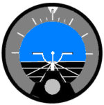
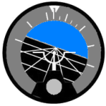
The display image corresponds to what the pilot would also see during visual flight (inside-out metaphor). The white line running across the display represents the horizon. The sky is blue, the earth is brown or black. The central point represents (approximately) the direction of the longitudinal axis of the aircraft and the horizontal lines next to it represent the transverse axis of the aircraft. The horizon sinks below the longitudinal axis when climbing, while it is above it when descending. If the aircraft is tilted to the left, the horizon appears tilted to the right and vice versa.
In the Eastern Bloc countries, a different display metaphor was used, which showed an aircraft seen from the outside in front of the horizon (outside-in metaphor, similar to the representation of the turn indicator ). The display image of these instruments is exactly the opposite of that of the western horizons, which can lead to uncertainties or incorrect reactions for pilots who switch from one system to another. At least one flight accident with a passenger plane can be attributed to it.
In addition, the longitudinal and lateral inclination can be roughly measured with the instrument. The outer ring is used to measure the bank angle using the small white triangle. The ring has markings at 10 °, 20 °, 30 °, 60 ° and 90 °. In the example, the scale is fixed to the horizon and the reference mark is fixed to the aircraft; but it can also be the other way around. The two inclined pairs of lines in the example image show bank angles of 15 ° and 45 ° when they are in alignment with the central vertical line. The central scale shows the pitch angle in 5 ° steps, using the center point for reading.
By changing the angle of attack, the angle of the aircraft changes to its motion vector. So the angle of attack increases z. B. in slow flight or with a large load. In correct horizontal flight, the artificial horizon shows this steeper in-the-air position by being slightly below the center point. In order to make flying easier, the pilot can adjust the angle between the longitudinal axis of the display and the longitudinal axis of the aircraft by means of a button.
Acceleration and cornering errors
The display of the artificial horizon is influenced by the acceleration error and the curve error. These are caused by the support. Both errors are based on the same phenomenon: Since it is not possible to differentiate between acceleration and gravity, the automatic straightening always takes place according to the apparent perpendicular . However, in accelerated conditions this deviates from the true earth perpendicular. In this way, the automatic straightening prevents the display from drifting in unaccelerated straight-ahead flight, but in turn always causes a new display error when accelerating. In principle , this problem can not be solved, even with an ideal top.
In order to reduce it, the gyro support is partially switched off in the event of a strong deviation of the apparent plumb bob from the current gyro position, as typically occurs in accelerated conditions. The behavior of the horizon under accelerated conditions differs among the models. A pilot is expected to know the behavior of "his" horizon instrument.
Operating limits
Usual operating limits for artificial horizons that are not specially designed for aerobatics are 100 ° to 110 ° for an inclined position and 60 ° to 70 ° for ascending or descending.
If one of these limits is exceeded, the cardan frame hits a stop and the display becomes unusable until the gyro is erected again. There are horizons that are fully suitable for aerobatics, but these are more expensive and are therefore only used in military aircraft.
Electronic gyro
Today there are hardly any mechanical gyroscopes in new aircraft, only electronic gyro instruments. Even if the designation gyroscopic instruments is still partially used, the electronic instruments naturally do not contain any mechanical gyros, but only electronic acceleration sensors. Good electronic gyroscopes require less maintenance, are superior to mechanical ones in terms of measurement accuracy and they usually also have less restrictive operating limits. In addition, your display can be seamlessly integrated into a glass cockpit .
The possible solutions range from inexpensive piezo sensors, such as those used in model helicopters , to high-precision, but very expensive ring laser gyroscopes.
In order to obtain the position in space, three such sensors have to be arranged perpendicular to each other and all current rotational speeds have to be integrated over time. This requires very precise measurements and appropriate processing of the measurement data. Additional acceleration sensors can supplement this calculation. There are already solutions that combine all measurements in a single integrated component.
literature
- Wolf von Fabeck: gyroscopes . Vogel Verlag, Würzburg 1980, ISBN 3-8023-0612-0 .
- P. Bachmann: Airplane instruments . Motorbuch Verlag, Stuttgart 1992.
- Peter Dogan: Instrument Flight Training Manual . 1999, ISBN 0-916413-12-8 .
- Jeppesen Sanderson : Private Pilot Manual . 2001, ISBN 0-88487-238-6 .
- Wolfgang Kühr: The private pilot . Technik II, Volume 3, 1981, ISBN 3-921270-09-X .
- Rod Machados: Instrument Pilot's Survival Manual . 1998, ISBN 0-9631229-0-8 .
- US Department of Transportation, Federal Aviation Administration: Instrument Flying Handbook , FAA-H-8083-15B, 2012.
Web links
Individual evidence
- ^ Accident of a Saab 340B of Crossair on January 10, 2000 near Nassenwil, west of Zurich. Official accident report http://www.sust.admin.ch/pdfs/AV-berichte//1781_d.pdf , illustration of the two instruments on page 63 of the report.


