
Magnet forming

The electromagnetic forming , true also as electromagnetic conversion referred to is an electro-dynamic high energy conversion method flat for cold forming (eg. B. sheets ), and a cylindrical semi-finished (for. Example, pipes , profiles ) made of electrically conductive materials using pulsed magnetic fields . The process is based on the so-called pinch effect .
The workpiece is positioned inside or in the vicinity of a coil and reshaped without contact by the Lorentz force , triggered by a short and high current pulse through the coil. When using this method for joining ( electromagnetic pulse welding ), the materials are brought together at very high speed and thus cold-welded.
Magnetic forming can partially replace conventional deep drawing, rolling , soldering , welding and gluing technologies in terms of production costs and product quality and is used in industries such as the automotive, aerospace, electrical, nuclear, packaging and kitchen appliance sectors.
Advantages and disadvantages


Magnet forming has the following advantages:
- The impulse can be precisely metered and reproduced. This enables metals to be pressed onto glass, plastics, composites or metals with high repeat accuracy.
- The effect of the magnetic force passes unhindered through materials such as glass, ceramic and plastic. Therefore, magnet forming can also be used under vacuum, a protective gas atmosphere or under clean room conditions.
- Due to their principle, magnetic forming systems do not require any mechanical contact with the workpiece, so there are no surface contamination or tool marks.
- Process time of <0.1 s
Disadvantages are:
- A good conductive material such as aluminum or copper is required
- the high magnetic fields can interfere with or damage electronic equipment
- the coil must be mechanically very stable and solid and is therefore expensive - its destruction is a potential hazard
- the suitability of the process or the design of the coil must be worked out in preliminary technological investigations
- the pulse generators are expensive and sometimes subject to wear
Physical basics
The magnetic forming process is based on the physical fact that a time-varying magnetic field induces eddy currents in neighboring electrically conductive bodies . The magnetic field exerts forces on these currents, the strength of which depends on the spatial gradient of the magnetic flux density and the size of the induced currents. The conductive body (sheet metal, pipe) experiences a force directed towards lower flux densities (see also eddy current accelerator ). The currents directed in the workpiece in the opposite direction to the coil current have the result that the coil and workpiece are pressed apart ( Lorentz force , Lenz's rule ).
The strength of the induced currents and thus the force acting on the workpiece depends, among other things, on the electrical conductivity of the material used. The method is therefore particularly suitable for silver, copper, aluminum and its alloys as well as z. B. suitable for brass.
For a short time, pressures of a few thousand megapascals act on the surface of the workpiece . Since forces act equally on the coil, the mechanical strength requirements for the coil construction are very high.
This so-called magnetic pressure is proportional to the square of the coil current and only prevails for the duration of the discharge of the capacitors. During this time, the workpiece absorbs the required forming energy in the form of a pulse . The efficiency is around 2 ... 25%. After the short acceleration phase, the material moves very quickly, especially with low mass. The speeds reach values of up to 300 m / s. As a result, the stresses occurring in the workpiece become so high that a flow occurs in the sense of forming technology. During welding, the material hits the joint partner at such high speeds and develops local mixing processes that also allow non-fusion-weldable material pairings to be welded. It is ensured that the pair of materials meet at a slight angle, as in explosive cladding, so that superficial oxide layers are removed by a supersonic shock wave.
technology
Strong and rapidly changing magnetic fields suitable for magnetic forming are generated in pulse generators by discharging charged capacitors over a period of a few tens of microseconds via a coil that is adapted to the workpiece geometry. A damped oscillation arises according to the inductance of the coil and the storage capacitor (resonant circuit).
As a switch u. a. Spark gaps ( Trigatrone ), Ignitrone and also semiconductor switches are used. While the thyristors, which have been in use for a long time, have too low a current rise rate for many applications, specially developed semiconductor structures - so-called GTO-like thyristors ( ABB ) and Super-GTOs (Siliconpower) - can generate the high frequencies required at high resonance frequencies Supply current rise rates (12… 50 kA / µs to 100 kA / µs). The charging voltages are in the one to two-digit kilovolt range. The energies can be found in the one to three-digit kJ range. Peak currents of up to 1 MA, typically 50… 200 kA, are reported.
The resonance frequency depends on the workpiece thickness: the skin depth should be less than this. It is limited at the top by the high-current switch and the wiring. This is why frequencies in the one to two-digit kHz range occur. Due to the strong damping, the quadratic current dependency and the already beginning movement of the workpiece, only the first half-wave of the oscillation is relevant.
The maintenance intervals and usage numbers range between a few and over 10 6 shots. The coils, the high-current switch, but also z. T. the capacitors.
particularities
driver
Even poor conductors such as stainless steel pipes can be formed with this process by surrounding the steel pipe with a driver made of a highly conductive material - a few turns of aluminum foil are often sufficient. The magnetic forces do not act directly on the steel here, but on the driver, which is used to shape the pipe.
The impulse or the mechanical energy introduced can be precisely adjusted via the level of the capacitor charge.
Field shaper

For the effective use of magnetic forces during forming, the distance from the coil to the workpiece must be as small as possible. In order to relieve the coil and / or to still be able to use the same coil with different workpiece dimensions, field shapers are used which make it possible to concentrate the electromagnetic force on certain areas of the workpiece.
The field shaper basically forms two coupled coils (outer diameter / inner diameter), is made of copper and must be slotted at least once along the coil axis so that the current can reach the inner diameter. Due to the skin effect, the current only flows on the field shaper surface. If, as in the picture, the length of the inner cylinder surface is shorter than that of the outer or coil, the effect is increased because the current density is higher there. The current flowing on the inner wall of the field shaper is also concentrated on the area that is close to the workpiece. Accordingly, there is a particularly high magnetic pressure in this area.
Fig. 2 shows an arrangement with a field shaper that is twice slotted for the purpose of assembly and a representation of the directions of the currents flowing in the coil, field shaper and workpiece.
Coil shapes and arrangements
There are three basic forms of magnet forming: compression, expansion and flat forming.
- compression
The most commonly used magnetic forming is compression. A cylinder coil that encompasses the workpiece is used as the work coil. The forces on the workpiece are directed radially inward and compress it or press it onto an inner core. This is shown in Figure 3.
Figure 4 shows the application of compression when pressing a tubular workpiece onto a joint yoke of a cardan shaft. The use of a field shaper ensures magnetic forces that are large enough to drive the wall material of the pipe into the recesses of the universal joint element.
Since a high degree of rotational symmetry of the forces occurring can be achieved with magnetic compression, it is usually superior to mechanical methods when pressing metal pipes onto ceramics, glass or brittle plastic.
- expansion
During the expansion, tubular workpieces are widened or pressed into a shape surrounding the tube. The work coil for generating the magnetic field suitable for this transformation is in this case a cylinder coil which is inserted into the tubular workpiece. This is shown in Figure 5. The forces acting on the pipe are directed radially outwards.
- Flat forming
Fig. 6 shows an arrangement for flat forming. The magnetic field is generated in the vicinity of a sheet metal lying on a die. The electromagnetic forces drive the sheet metal into the recess of the die. The magnetic field replaces the conventional mechanical stamp here. In this example, the flat coil used to generate the magnetic field has the shape of a clock spring ( Archimedean spiral ). It is attached above the workpiece parallel to it.

Figure 3: Compression of a pipe

Image 4: Connection of shaft and joint using compression

Fig. 5: Expansion of a pipe

Fig. 6: Flat forming
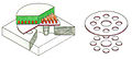
Fig. 7: Separation using a flat coil


The three basic types of magnetic forming described can be used for forming, connecting and joining, but also for cutting if suitable tools are used. Figure 7 illustrates this using the example of a flat coil. At the designated places, the workpiece material is driven into the recesses in the base and separated from the workpiece. In the same way, pipes can be provided with holes of any shape or cut.
literature
- KG Günther, H. Schenk: Magnet forming . In: Günter Spur, Theodor Stöferle (Ed.): Handbook of manufacturing technology . Hanser Verlag, 1985, ISBN 978-3-446-13947-3 , pp. 1342–1356 ( limited preview in Google Book search).
Web links
- Magnetic pulse welding and crimping at the Welding Training and Research Institute in Munich
- Magnet forming in youth research
swell
- ↑ https://www.iwu.fraunhofer.de/content/dam/iwu/de/documents/Broschueren/IWU-KB-Elektromagnetische-Umformung.pdf
- ↑ Fast magnetic conversion. Corporate publication of Puls-Plasmatechnik GmbH, Dortmund 1990.
- ↑ Kurt Lange: Umformtechnik Handbook for Industry and Science: Volume 4: Special processes, process simulation, tool technology, production. , Springer Verlag 2013, 815 pages, page 30
- ↑ dto. Page 45
- ↑ dto. Page 67
- ↑ http://www.siliconpower.com/datasheets/Ultra-fast%20Thyratron%20Replacement%20-%20JW%20KB%20052317.pdf John Waldron, Ken Brandmier: Ultrafast Solid State Thyratron Replacement , lecture at the 44th International Conference of Plasma Science , Atlantic City (NY / USA) May 2017, page 15
- ↑ http://www.astrol.ch/view/data/2963/Articles/ABB%20-%20Discharge%20Switches%20(ICHSF2006).pdf A. Welleman, W. Fleischmann: High Power Semiconductor Devices and Solid State Switches for Pulsed Discharge Applications , lecture at the 2nd International Conference on High Speed Forming 2006
- ↑ various references from ABB
- ↑ John Waldron, Ken Brandmier: Solid State Discharge Switch Replacements , lecture at the Pulsed Power Conference in Brighton / UK, June 2017, page 17
- ↑ https://www.researchgate.net/publication/229327779_Electromagnetic_forming-A_review V. Psyk, D. Rischa, BL Kinseyb, AE Tekkayaa, M. Kleiner: Electromagnetic forming — A review in Journal of Materials Processing Technology 2010, on researchgate for Provided by M. Kleiner 2014
- ↑ Robert Hahn: Tools for impulse magnetic hot joining of profiles made of aluminum and magnesium alloys , dissertation at the TU Berlin 2004, page 130