Raised cosine filter
The raised cosine filter , also known as the cosine roll-off filter , is an electronic filter used in digital signal processing , a sub-area of communications technology , which is used to form signal pulses . It belongs to the group of Nyquist filters.
This filter fulfills the first Nyquist condition as an essential property . This means that signal pulses which follow one another in time and which are formed with this filter have zero points in the time grid of the sampling signal and thus do not affect preceding and following pulses at the sampling times. This filter thus allows a temporally discrete signal transmission in which no intersymbol interference (ISI) occurs.
presentation
A raised cosine filter always has the properties of a low-pass filter and is implemented in digital filter structures (e.g. as a filter with a finite impulse response (FIR)). Its transfer function (the amount of the frequency response) is constant up to a certain frequency, which depends on a roll-off factor , and furthermore it drops cosine-shaped to the value zero for higher frequencies. The name of this filter is derived from this fact.
The raised cosine filter is used in digital signal transmissions to shape the transmission pulses used on the transmission channel. The transmission pulses, or also called symbols, represent the discrete information to be transmitted. The transmission channel can, for example, be a radio channel or also wired. Applications are therefore in digital transmissions, such as in the mobile communications sector .
This filter is implemented in digital signal processors (DSP), application-specific integrated circuits (ASIC) or freely programmable digital circuits, the so-called field programmable gate arrays (FPGA).
Transfer function
The transfer function of this filter, apart from the symbol rate (1 / T), which is always essential in discrete-time transmission systems , depends on a special factor, the roll-off factor α. The designation α for the roll-off factor is not chosen uniformly in the literature. There are also terms like r or β.
With this factor, which can take values between 0 and 1, the steepness of the transfer characteristic is significantly influenced: For the limit value α = 0, an ideal, non-causal low pass with a rectangular transfer function results. For α = 1 there is a maximally flat cosine edge. For intermediate values, the associated frequency response is approximately constant in a certain range and only then drops with a somewhat steeper cosine edge, as shown in the following figures:
The larger the roll-off factor, the more the bandwidth of the filter increases. The bandwidth can only increase up to a maximum of 1 / T symbol rate (due to the time-discrete property). A smaller roll-off factor leads, due to the filter flank becoming steeper, to larger undesirable overshoots, which ultimately result in greater phase noise and thus insufficient pulse shaping in real transmission systems . This can lead to errors in the demodulation.
In practice, however, a roll-off factor below 0.5 in the range from 0.2 to 0.5 is usually used, as this can save valuable bandwidth. For example, the UMTS mobile radio standard uses a roll-off factor of α = 0.22 for the pulse filters used therein.
The bandwidth of the filter with the symbol rate f s = 1 / T is calculated in the baseband as:
Mathematical description of the transfer function
The transfer function H (f) normalized to 1 is given by
with the impulse response
- ,
where the singularities at and through continuous continuation have been eliminated. The impulse response has the course of the si function , which has zeros for multiples of the symbol duration T and is therefore free from intersymbol interference .
Symbol rate
The transmittable symbol rate of a raised cosine filter with a given roll-off factor α and a bandwidth B is:
Since double the bandwidth is available in the bandpass range:
In the baseband, the bandwidth efficiency in the borderline case of α = 0 is 2 symbols / s per Hertz bandwidth or, in the case of binary transmission, 2 Bit / s per Hertz bandwidth and is halved if the bandwidth requirement is doubled in the bandpass range. In practical implementations, roll-off factors in the range α = 0.3 (30%) are selected, which results in a spectral efficiency of approx. 1.5 bit / s per Hertz bandwidth in binary transmission.
Eye diagram
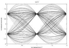
The following figures show eye diagrams of raised cosine filters with various roll-off factors. This can be used to assess the quality of the signals.

Roll-off factor 0 ( ideal low pass )
|
Root raised cosine filter
The root raised cosine filter , shortly RRC corresponds (Engl. The root root ) from the raised cosine filter.
See also
literature
- John B. Anderson: Digital Transmission Engineering . 2nd Edition. Wiley Interscience, Lund, Sweden 2005, ISBN 0-471-69464-9 .
- Kaveh Pahlavan, Allen H. Levesque: Wireless Information Networks. 2nd edition, John Wiley & Sons Ltd, New Jersey 2005, ISBN 978-0-471-72542-8 .
- Amithaba Bhattacharya: Dig Communication. Tata McGraw Hill Education Privat Limited, New Delhi 2006, ISBN 0-07-059117-2 .
- Eduard Säckinger: Broadband Circuits for Optical Fiber Communication. John Wiley & Sons Ltd, New Jersey 2005, ISBN 0-471-71233-7 .
- John Dunlop, Demessie Girma, James Irvine: Digital Mobile Communications and the TETRA System. John Wiley & Sons Ltd, Chychester 1999, ISBN 0-471-98792-1 .


