Rotary heat exchanger


A rotary heat exchanger (also rotary heat exchanger , heat wheel , air preheater or LUVO called) is a heat exchanger , wherein the heat recovery allows an air stream to another. A rotating storage mass is alternately warmed up by one air flow and cooled by the other.
Rotary heat exchangers for the use of waste heat from the process air from industrial processes are also called air preheaters .
Function description
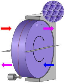
The rotor consists of numerous channels parallel to the axis. The heat storage capacity of the duct walls is used. The warm exhaust air is blown through half of the rotor and the duct walls warm up. If the rotor continues to rotate, the heated ducts reach the area where cold outside air flows through them; this warms up on the warm channels, whereby the channel walls cool down. When the two air flows are arranged in opposite directions, the rotor has a cold and a warm side and corresponds to a counter-flow heat exchanger.
In the simplest arrangement shown in the picture, the channels are still filled with warm exhaust air when the rotor continues to turn and reaches the area of the opposite air flow. The co-rotation of the air always creates a small proportion of circulating air, regardless of the pressure gradient , through which the exhaust air mixes with the supply air. A certain amount of exhaust air is also transferred to the supply air through leakages on the rotor, which are driven by the pressure gradient between the air flows. Because of these undesirable air flows, the fans for supply and exhaust air have to provide a slightly higher output than necessary for the actual air exchange.
The proportion of recirculated air can be prevented by not diverting the supply air from the outside into the inside of the building in a small area (circular sector), but diverting it in a so-called flushing chamber and blowing it in the opposite direction through the rotor into the exhaust air duct. This requires a pressure gradient between fresh and exhaust air . The rinsing chamber makes a further increase in the fan output necessary. Both measures reduce the efficiency, as the fans have to generate around 3–10% more power.
Construction in ventilation and air conditioning technology
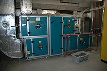
For fresh air circulation in buildings, the rotor is usually made of foils with sufficient heat capacity. Like corrugated cardboard, a smooth and a corrugated layer of the film are rolled up together until the desired outer diameter is reached. The air flow can pass through the fine channels between the shafts. Typical film thicknesses are between 0.05 and 0.12 mm. The channels are usually 1.4 mm to 2.5 mm wide and are as long as the rotor is thick, usually 200 mm. Since condensation can occur in the heat exchanger, the material must be corrosion-resistant. Aluminum foil or stainless steel foil is often used. Plastic film (such as PET ) is also used in the home for controlled living space ventilation . In the event of insufficient cleaning, the latter, as well as asbestos or fiberglass-supported fleece, can pose health risks through fouling .
Rotary heat exchangers are manufactured with rotor diameters of approx. 40 cm to over 6 m and, depending on the size, run at speeds of around 3 to 25 revolutions per minute. It is mostly driven by a three-phase motor ( asynchronous motor ) via a belt drive . The motor power of the drive is around 30 W per m³ / s air volume.
Air preheaters (LUVO) in power plant technology
The air preheater is heated by the flue gas from the boiler and is used to preheat the combustion air. The LUVO is usually the last heating surface in the flue gas flow before the flue gas outlet or chimney.
It extracts heat from the flue gas and heats the fresh air drawn in by fans . This transferred heat share no longer has to be provided by the fuel , which is why the heating surfaces can be dimensioned smaller. For this reason, air preheaters are designed up to the maximum possible limit of the process technology, which is determined by the dew point of the flue gas. The heated combustion air also ensures that the fuel-air mixture is more ignitable. Since the LUVO extracts heat from the flue gas, it is cooled down and leaves the chimney at a lower temperature . The exhaust gas loss of the boiler is reduced and the boiler efficiency increases to the same extent.
Air preheaters are particularly susceptible to corrosion before all other components of the boiler because they are located at the cold end of the flue gas path and the low fresh air temperature favors the proximity to the dew point temperature of the flue gas. For this reason, the laminated cores that form the storage mass of the LUVO are made of corrosion-resistant materials or are enamelled . A steam recuperator is often connected upstream of the LUVO in order to ensure that the temperature does not fall below the dew point.
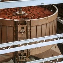
The Ljungström regenerator , which is designed as a cross-countercurrent, is usually used for high outputs . Its slowly rotating storage mass consists of tightly packed and folded sheet steel packages, which alternately absorb and release the flue gas heat according to the rotation.
In the less commonly used Rothemühle regenerator (the name - giving company is now part of Balcke-Dürr ), the storage mass is static, while the air hoods on the top and bottom rotate and thus alternately flow through the preheater.
In the case of low outputs, air preheaters in plate construction or as steel tube bundles are used (recuperative heat exchangers).
Conveying energies
The operation of a rotary heat exchanger requires not only the drive energy of the rotor motor but also additional conveying energy for the amount of air flowing through. This can be divided as follows:
- Overcoming the pressure losses caused by the rotor
- Compensation of the air flow rate through rotation on the hot and cold side.
- If necessary, compensation for the air flow rate and pressure loss in the rotor wheel and in the fresh and exhaust air ducts that are lost due to the flushing.
- Compensation of the air flow rate and pressure loss due to leakage.
- If necessary, overcoming the pressure loss of the throttle valve to ensure the required overpressure
- Compensation for pressure losses due to the extension of the exhaust and fresh air ducts, which is necessary to merge the air flows at the heat exchanger.
Accurate detection is made more difficult by the fact that the varying pressure difference between fresh and exhaust air ducts and the slip ring seals result in complex flow conditions.
The following additions to the pressure loss of the rotor wheel are roughly assumed for the calculation in order to determine the additionally required conveying energy:
- Rotary heat exchanger with co-rotation: 120–180%
- Rotary heat exchanger with flushing: 200–280%
Example: pressure loss of a rotary heat exchanger with co-rotation = 140 Pa, addition = ~ 210 Pa. Total pressure loss = 140 Pa + 140 Pa + 210 Pa = 490 Pa.
Leaks
A general distinction is made between external and internal leakage in heat exchangers. External leakage is an undesired exchange of air through the outer housing wall. The following internal leaks between the air flows occur inside the housing:
- Co-rotation occurs in two places - once on the warm side and once on the cold side - regardless of the prevailing pressure gradient and inevitably causes an unwanted proportion of circulating air. Co-rotation requires increased air volume flows on the cold and warm side.
- Purge air is an optional additional measure and prevents co-rotation on the warm side (co-rotation on the cold side is usually not prevented). To compensate for the scavenging air, increased air flows are required on both sides of the rotor wheel.
- Leakages at the seal between the rotor and the housing occur depending on the local pressure gradient. The pressure gradients are different on the hot and cold side and differ by twice the rotor wheel pressure loss (~ 300 Pa). The manufacturer's information on leakage (exhaust air to supply air) usually relates to a pressure gradient of 0–20 Pa (supply air to exhaust air) on the warm side and is a maximum of 3% of the supply air volume flow according to DIN. The fact that the leakage from the exhaust air to the supply air occurs despite the opposite pressure gradient is due to the co-measured rotation. This is different with the leakage on the cold side: Because of the increased pressure gradient there, it can be estimated to be ~ 5 times the leakage on the warm side. The actual pressure gradient is decisive for the amount of leakage. This usually differs considerably from the above test condition 0–20 Pa. To compensate for the leaks, increased air volume flows are required on the hot and cold side.
Moisture transfer
Depending on the application and operating situation (cooling or heating of the useful air and temperature pairing), the transfer of water vapor from one to the other air flow is different. In addition to condensation, porous storage material also allows sorption . Roughened aluminum also enables a certain sorption in capillary gaps. In contrast, special absorbent coatings enable a significantly stronger exchange of moisture.
Applications
Rotary heat exchangers are used in ventilation and air conditioning technology in ventilated buildings as well as in the offshore area (e.g. cruise ships). They are also increasingly being used in process air technology, both in the hot air range up to 650 ° C and in drying ovens in paint shops.
In moderate latitudes, the main focus is on warming the supply air in the cold season; At high outside temperatures, the heat exchanger can cool the outside air drawn in by heating the exhaust air. However, the moisture transfer desired in winter is often undesirable in summer.
Advantages:
- In the case of condensation, a one-sided temperature efficiency of up to 80% can be achieved using the countercurrent process. Further energy savings result from lower power requirements on the air heater or air cooler.
- Low payback periods (between 1 and 5 years)
- Depending on the size, suitable for very high air volumes of up to 180,000 m³ / h.
- Self-cleaning effect against coarse (e.g. flies, leaves) or dry soiling (e.g. dust) through constant change of air direction between supply air and exhaust air. Impurities in the fresh air are blown out with the exhaust air, as are between the exhaust and supply air.
- Low construction depth (100–250 mm)
- The supply air temperature can be lowered by reducing the speed (or increased in summer). However, this reduces the efficiency of the heat recovery.
- In addition to heat, humidity can be recovered (with a water-absorbing coating on the heat exchanger) and the energy requirement for air humidification can be reduced in winter.
- In most cases, the condensation water does not need to be drained off, since any condensation water that may occur is absorbed by the supply air even without a water-absorbing coating on the heat exchanger. Only with extremely humid exhaust air, such as occurs in a swimming pool, or with already largely saturated air, condensation can occur.
Disadvantage:
- More susceptible to failure than z. B. Plate heat exchangers .
- The merging of outside and exhaust air ducts requires increased investment and increases the energy consumption of the fans.
- No protection against smoke and flashover .
- Circulating air proportions through co-rotation
- Leakage through sliding seals
- Circulating air proportions and possibly leakage nice heat recovery rate or efficiency
- No complete separation of supply air and exhaust air. Residues of the air pollution in the exhaust air can get back into the supply air in a diluted form through the heat exchanger. This is problematic in the case of harmful exhaust gases or strong odors in the exhaust air. With a correct fan arrangement, the mixing of the air flows can be greatly reduced with a rinsing chamber.
- Hygienic problems because the rotating storage mass brings fungi, bacteria or viruses from the exhaust air into contact with the supply air. Some special designs are permitted for certain areas in hospitals, but the use of rotary heat exchangers should be checked on a case-by-case basis. Germ-inhibiting surface coatings are also used, but then carry the risk of the formation of multi-resistant germs.
- Seal wear in the supply air
- Icing of the (transverse) seals with condensation in winter
- Pressure gradient between outside and exhaust air required when using purging chambers. If the pressure gradient is too great, very large amounts of flushing and leakage air up to housing deformations with impairment of operation are possible.
- Additional electricity consumption due to increased air volume for co-rotation, flushing and leaks.
- The size (wheel diameter) is significantly larger than the cable cross-section.
- The lifespan is often only 10–15 years.
literature
- VDI Society for Technical Building Equipment: VDI guideline VDI 2071, heat recovery in ventilation and air conditioning systems. Beuth-Verlag, 1997
See also
Individual evidence
- ↑ Rotary heat exchanger, manual for planning, installation and operation, Hoval company website, heat recovery (PDF) (Art. No. 4 211 004, edition 07/2014) accessed on October 14, 2014.

