
Voith-Schneider drive


The Voith-Schneider-Drive or Voith-Schneider-Propeller ( VSP ) is a ship propulsion system in which the thrust can be adjusted in terms of magnitude and direction without changing the speed . The steering takes place by setting the incline for the direction ahead-back (travel) and by setting across the ship ( rudder ). This type of control gives the ship maximum maneuverability and allows a very fine dosage of the thrust and extremely fast change of the thrust direction without changing the speed. If the ship is equipped with two or more VSPs, the ship can move in any direction, including sideways (traversing).
The Voith Schneider drive was invented by Ernst Schneider . It has been developed and produced by the Voith company in Heidenheim and St. Pölten since 1926 .
technology
The blades of the Voith-Schneider drive move on a circular path and perform an additional, superimposed pivoting movement. The axis of rotation of the VSP is vertical.
VSP work at very low speeds. They are only around 25 percent of the speeds of screw propellers with comparable sizes and powers. The low speed is associated with high torques, which make a robust construction necessary, which, however, has the disadvantage of increased weight. VSPs are built up to approx. Four megawatts of power consumption, with wing diameters of up to four meters. The wing length is up to 82 percent of the wing diameter. They are mostly driven by diesel engines or electric motors .
In contrast to the screw propeller, the axis of rotation and the direction of thrust are perpendicular to each other in the VSP. Therefore there is no preferred direction of thrust for the VSP. The Voith-Schneider drive is a controllable pitch propeller that allows the thrust to be continuously varied in terms of size and direction. Since the VSP generates drive and steering forces at the same time, additional attachments - such as shaft blocks, ship rudders, gondolas, shafts, etc. - are not required for ships with VSP.
The rectangular beam area of a Voith-Schneider drive is roughly twice as large as that of a screw, given the installation conditions.
principle

Swivel blade propeller (principle)
Forces act on a surface (blade, wing) placed in the flow of a fluid (water, air, etc.) at an angle with an angle of attack α or moved in a stationary fluid: the drag force (in the direction of movement) and the dynamic lift or propulsion (transverse direction of movement). This buoyancy force can be used by means of a rotating machine in that inclined surfaces move on a circular path. However, if the surfaces maintain their angle relative to the respective tangent, all forces cancel each other out. Therefore, the angle of attack of the surfaces must be changed during the orbital movement. It is useful here that a positive angle of incidence offset by 180 ° is offset by a negative angle of incidence (not necessarily the same size) (there are also other concepts, see and folding-wing rotor ). The angle changes continuously in the two movement areas in between. The greater the angle of attack, the greater the dynamic lift (only applies up to a certain limit) whose power is used.
The surfaces are designed as symmetrical streamlined bodies in order to minimize the drag force in the direction of movement (circular path). The use of wing profiles is also possible. In this case, the profile on one side of the circular path increases the dynamic lift compared to that of the inclined symmetrical flow body. On the opposite side (offset by 180 °), however, practically only the inclined position of the profile is effective.
Schneider recognized and described that such a propeller can be controlled in a simple and advantageous manner (compared to other swivel vane principles) and used as a ship propulsion system. The control device proposed by him is located inside the rotor circuit. A compact structure is possible.
The Voith Schneider propeller (VSP) can in principle be used as a turbine, a pump or blower or as a drive.
Use as a turbine
The stationary rotor is flowed against by the fluid in one direction and is set in rotation (torque) by the force generated in the direction of movement (tangential). Energy is obtained from the current (e.g. wind, water). In contrast to conventional wind turbines with a vertical axis of rotation ( Savonius rotor , Darrieus rotor etc.), however, a VSP must be turned into the wind (or in the direction of flow of the water). A vertical axis of rotation is useful, but not absolutely necessary. Applications as a turbine have not yet become known.
Use as a pump / blower
The stationary rotor is driven by a motor and set in rotation. There is a force on the fluid and a flow in one direction. The axis of rotation can have any position. Recently, it has been proposed to flow into Flettner rotors with Schneider rotors in order to realize an aircraft capable of short takeoff.
Use as a drive
The rotor mounted on a vehicle that is movable in a fluid (preferably water) is driven by a motor. Propulsion is created in one direction that can be used to propel a ship (e.g. a ship). In principle, however, a vehicle (on water or on land) can also be driven in this way if the rotation takes place in air. Vertical or approximately vertical axes of rotation are preferably used.
The cutter rotor is currently only used to drive ships. The driving direction (without rudder) and the driving speed (without changing the speed) can be changed quickly and easily. The kinematics of this control are described below.
kinematics
Control (speed)

Control (direction of travel)
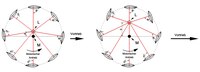
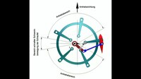
The blades rotate around the center M of the orbit and can each be pivoted around the pivot point S. A connecting line from the pivot points to a guide point L (position a) that is shifted in relation to M must always form a right (or approximately right) angle with the axes of symmetry of the blades. It can be seen that, under this condition, the blades are rotated during one revolution and, in the areas of their inclination with respect to the respective tangent to the orbit, a dynamic lift is generated in the same direction, which results in propulsion. If the guide point L is further removed from the center point (position b), the inclination of the blades increases and thus also the propulsion. The speed of the ship can thus be increased simply by shifting the control point (without changing the engine speed, which of course can also be made). If L is rotated by an angle β by M, the propulsion force and thus the direction of travel are also shifted by this angle. If L is rotated by 180 ° (or shifted over M), the direction of travel changes from forwards to backwards (or vice versa).
Realization of the tailoring principle

The principle can be implemented in a simple manner if each blade is rigidly connected to a rod that can slide linearly in a rotating guide bearing (see animation for a blade).
However, it makes sense to expand the principle in such a way that kinematic concepts that cause other (suitable) blade positions by relocating a guide bearing and thus result in speed changes or changes in the direction of travel are seen as a possibility for realizing a VSP. The imaginary master point L * (or the imaginary master axis) is no longer identical to the real master bearing that is also present here, but moves back and forth.

VSP with linkage
VSP with linkage
VSP with coupling gear
VSP with coupling gear

So-called coupling gears (linkage gears ) are used to implement such kinematics . Their individual parts are connected by joints .
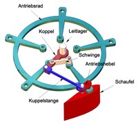
A simple implementation option is shown schematically in the picture. The blades are connected by arms A to the guide bearing, which represents the guide point or the guide axis. The arms can rotate independently of one another around the guide bearing on which they are stacked. The blades are rotatably mounted about their axes S in the motor-driven drive wheel and are connected to the arms via levers H and joints G. The animation shows that there is a drive in a certain direction.
The concept shown in another picture is a little more complicated. The animation shows the rotation of a shovel moved by a coupling gear. Coupling gears can be varied in many ways, so that an implementation option can be found for every desired blade adjustment.
The example shows a variant in which a larger drive range is effective.

Control of a VSP
In order to control the drive in the manner described above (i.e. to move the guide bearing), the guide bearing is equipped with a spherical bearing. A control pin provided with three spherical areas engages with a ball in this spherical bearing. The middle ball is held in a bearing fixed to the frame, while the upper ball is guided in a bearing that can be displaced by two hydraulic cylinders arranged at right angles (see picture). The control pin can be pivoted in all directions around its central spherical bearing. The hydraulic cylinders are controlled with the help of a control stick or joystick. In this way, the guide bearing can be moved in the required manner. As described above, the movement of the stick controls both the direction of travel and the speed.

Cycloidal trajectory of a propeller blade
Cycloidal trajectory of a propeller blade (the drive areas are marked in red)

When the ship (and thus the rotor) moves at a certain speed, the blades move on a cycloid path through the water due to the rotation of the rotor . VSP are therefore also known as cycloidal propellers or rotors. The shape of the cycloid depends on the ratio of the ship's speed to the speed of rotation of the rotor.
The possibility of moving each blade individually with a servomotor was also considered. A coupling gear for the blade control could then be dispensed with and the blade adjustment z. B. be carried out by a computer (problem: energy and signal transmission to the servomotors). A guide bearing and its mechanical adjustment could be dispensed with. Nothing is known about the implementation of such a solution.
It should also be mentioned that the rotating wheel body (with rods) is encapsulated in a cylindrical casing and thus protected against seawater. The blades protruding through the casing and the bearing for the wheel body are sealed by sealing sleeves. In the photo shown at the beginning, the wheel center is black, while the stationary parts are blue.
use

Due to its excellent properties for increasing the maneuverability of ships and its very good controllability, the Voith-Schneider drive is used in tow vehicles , double-ended ferries , passenger ships , buoy jigs , floating cranes , oil rig supply ships, bow control modules and vehicles that require high maneuverability or against wind or current and shafts have to be kept in place (dynamic positioning) . In inland shipbuilding, the Voith Schneider drive is also used to drive push convoys . In military use, the propeller is used in minesweepers . Even before the Second World War , two minesweepers of the 1935 type, as well as some of the mine clearing boats in the Capella class, so called after the war, were each equipped with two Voith Schneider drives.
Literature (selection)
- Kurt Benz: The Voith Schneider Propeller as a ship model drive. Scholz, Wolfsburg 1980, ISBN 3-922414-10-9 .
- Theodor Vieweg: The VSP drive in a ship model. Neckar-Verlag, Villingen-Schwenningen 1983, ISBN 3-7883-0187-2 .
- Birgit Jürgens, Werner Fork: Fascination with Voith Schneider Propellers. History and technology. Koehlers Verlag, Hamburg 2002, ISBN 3-7822-0854-4 .
Web links
- short description from the manufacturer
- Interactive Voith Schneider Propeller program, functional demonstration for testing
Individual evidence
Attention! With DEPATISnet information, an error message often appears the first time it is clicked. The second time the link works.
- ↑ DEPATISnet | Document DE000000453823A. Retrieved December 5, 2017 .
- ↑ DEPATISnet | Document DE000000413896A. Retrieved November 21, 2017 .
- ↑ Patent EP0795466 : Cycloidal systems with double or multiple wing systems. Registered on September 17, 1997 , published on July 18, 2001 , applicant: Voith Hydro GmbH, inventor: Amelang Andreas.
- ↑ Achmed Khammas - The Book of Synergy - Part C - SPECIAL WIND ENERGY SYSTEMS. Retrieved November 22, 2017 .
- ↑ Patent EP1964774 : Aircraft with rotating cylinders to generate lift and / or propulsion. Registered on February 27, 2008 , published on September 3, 2008 , applicant: Bauhaus Luftfahrt EV, inventor: Dr. Jost Seifert.
- ↑ Patent DE102007009951 : Aircraft with rotating cylinders to generate lift and / or propulsion. Registered on March 1, 2007 , published on July 31, 2008 , applicant: Bauhaus Luftfahrt EV, inventor: Jost Seifert.
- ↑ DEPATISnet | Document DE000000704008A. Retrieved November 21, 2017 .
- ↑ DEPATISnet | Document DE000019811251C1. Retrieved November 21, 2017 .
- ↑ DEPATISnet | Document EP000000785129B1. Retrieved November 21, 2017 .
- ↑ DEPATISnet | Document DE000000500340A. Retrieved November 21, 2017 .
- ↑ DEPATISnet | Document DE000004337761C2. Retrieved November 23, 2017 .