
Hiking compass

A hiking compass , militarily also a marching compass , is a light pocket compass of various types and mostly of moderate accuracy, which is used for orientation in the field . A hiking compass usually has a 360 ° angle rose , while a military marching compass often uses a 64 (00) 'line angle rose . In shipping, a steering angle of 5 ° is seen as sufficient. This corresponds to one line in a 64 'line angle rose.
Compass types

Pocket compass

Ruler compass

Mirror compass

Mirror compass
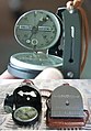
Linseatic compass

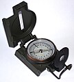
Prism compass


Hiking compasses can be divided into different designs, such as
- Pocket compasses
- Compasses with a mostly round housing, without a bearing or angle measuring device.
- Ruler compasses, plate compasses
- Compasses in which the compass box is rotatably mounted on a transparent base plate. The base plate has a contact edge for map work, often also different length and coordinate scales. Bearing devices are usually not available with straight-line compasses.
- Mirror compasses
- Compasses with a foldable mirror, which allows you to observe the target object and the magnetic needle at the same time while bearing.
- Linseatic compasses
- Compasses with a magnifying glass that allows you to read the graduation of the compass while bearing.
- Prism compasses
- Compasses which, by means of an optical deflection and magnification system, allow you to observe the target object while bearing and at the same time observe the graduation of the compass. They are designed for particularly precise directional bearings; Pure prism compasses usually lack the equipment for map work or for fixing the found direction using a rotatable compass socket.
- Special designs
- such as binocular compasses , thumb compasses , etc.
Often, combinations of these basic types can also be found, particularly often e.g. B. Mirror compasses with a transparent ruler base plate.
On the other hand, hiking compasses can also be divided into different types of use, such as
- Map compasses
- Map compasses are used for map work, d. H. the removal of a course or bearing direction from the map, or the transfer of a course or bearing direction to the map. The prerequisite for this is at least the existence of a mooring edge. A transparent base plate makes work easier, a transparent compass box extends the measurement options.
- Bearing compasses
- Bearing compasses have facilities for more accurate bearing, such as B. a mirror or prism optics. Facilities for card work are often not available.
accuracy
As a rule, hiking compasses have to be inexpensive, light and robust, while the demands on accuracy are relatively low. The accuracy of the various types of compass that can be used as a hiking compass is therefore usually in the range of a few degrees :
| Prism bearing compasses: | ⅓ ° - ½ ° | |
| Binocular bearing compasses: | approx. 1 ° | |
| Linseatic bearing compasses: | approx. 2 ° | |
| Mirror compasses: | approx. 1 ° - 3 ° | |
| Ruler compasses: | approx. 3 ° - 5 ° |
In addition to this setting and reading uncertainty, there are also the daily fluctuations in the earth's magnetic field (e.g. ± 0.5 °), the uncertainty in the knowledge of the current declination (e.g. ± 0.5 °) and inaccuracies in the transmission of the Heading angle into or out of the map (e.g. ± 0.5 °).
In the case of particularly high demands on accuracy, a prism bearing compass with a clear reading accuracy of 1 ° or less is recommended for work in the field (with clear target recognition at the same time). One is for the cards work then maps protractor preferable because it is more accurate than a hiking compass and the magnetic needle is obsolete on the map.
Magnetic declination and needle deviation
Definitions
In German-speaking countries, the differences between geographic north, grid north and magnetic north are only a few degrees and can be ignored for most orientation tasks. In the case of higher accuracy requirements or in areas with greater declination, however, the various north directions must be carefully differentiated:

Magnetic declination: The local magnetic north can differ significantly from true north. The magnetic declination for 2010 is shown.
Meridian convergence:
The meridians of the geographic network (red) are usually inclined to the lines of the map grid (gray).


- Geographic north, i.e. the direction to the geographic North Pole . The longitudes ( meridians ) of the earth run in a geographical north-south direction.
- Grid north, i.e. the direction of the map grid lines (if any). While all longitudes run towards the North Pole, that is to say approach one another (“converge”), the grid lines run parallel to one another according to their definition. In a meridian strip , therefore, at most one grid line can coincide with a longitude circle . The other longitudes and grid lines intersect at angles which increase with the distance from the equator and with the distance from the central meridian of the meridian strip.
- Magnetic north, i.e. the local direction of the field lines of the earth's magnetic field . The compass magnetic needle points in magnetic north.
These north directions are usually not identical:
- The difference between magnetic north and true north is known as magnetic declination . It is currently only about 0.5 ° to 3.5 ° East in German-speaking countries, but reaches z. B. in Canada, USA, South Africa and New Zealand sometimes 20 ° or more and can then no longer be neglected. If magnetic north is west of geographic north, the declination is called westerly or is counted as negative , if magnetic north-east of geographic north, the declination is called east or counted as positive .
- The difference between grid north and geographically north is called meridian convergence . It has the value zero on the central meridian of a meridian strip and on the equator and increases towards the edges of the strip and towards the poles - in the UTM grid up to a maximum of ± 3 ° and in the Gauß-Krüger grid up to a maximum of ± 1.5 °. If the grid north is west of geographic north, then the meridian convergence is counted as negative ; if the grid north is east of geographic north, the meridian convergence is counted as positive .
- The difference between magnetic north and grid north is called the needle deviation . It corresponds to the difference between declination and meridian convergence. If magnetically north west of grid north, the needle deviation is counted as negative , if magnetically north east of grid north, then needle deviation is counted as positive .
The official topographic maps in Germany and Austria are degree department maps, i. H. the lateral boundaries of the map field are meridian lines, i.e. they run in a geographical north-south direction. In many maps, meridian lines are also marked on the edge of the map, but not drawn through; if necessary, the user can draw them in with a ruler and use them as reference lines for true north.
In Switzerland, the map edges of the topographic maps coincide with grid lines. In these maps, the side map frames can be used as reference lines for the grid north. In many modern maps, map grids are also printed directly into the map field and can be used as reference lines. Geodetic map grids are not to be confused with the search grids printed on some maps (“Hotel Müller see B-7”), which have no defined relationship to the north direction.
Angle correction
In the field, the magnetic needle serves as a reference direction for angle measurements with the compass; it always points to magnetic north. If an angle taken from the map (i.e. determined with respect to geographic north or grid north) is to be transferred to the terrain, or if an angle taken from the terrain (i.e. determined with respect to magnetic north) is to be transferred to the map, the difference between the north directions involved must be taken into account become. Topographic maps usually contain information on magnetic declination or needle deviation for the area shown.
The following correction options are available:
- The correction can be done by not aligning the compass needle with the north mark of the compass socket, but in such a way that it shows the relevant declination or needle deviation on the graduation of the socket, depending on whether geographic north or grid north is used as the reference direction on the map shall be. In addition to the usual graduation, some compasses have a declination scale which, starting from the north, counts the angles with a positive increase both to the west and to the east.
- Some compasses have a “declination correction”. The user can turn the north mark and the can grid (see below) by hand or with a small screwdriver by the correction angle so that the can grid points to true north (or grid north) when the north mark is aligned to magnetic north using the magnetic needle. Sometimes separate adjustable declination marks are also available.
- The course angles can be converted into one another by calculation (and the position of the compass socket corrected accordingly if necessary). Care must be taken to ensure that the signs are correct. A rule of thumb is: "From the wrong to the true course with the true sign, from the true to the wrong course with the wrong sign." The "true" course is the course related to geographically north or grid north (cf. correct ), the "wrong one . " (see. "price of the related magnetic north miss-setting ). Should z. If, for example, a course related to magnetic north is converted into a course related to grid north (false → true), the needle deviation must be added, taking into account its given sign. If a course related to grid north is to be converted into a course related to magnetic north (true → false), the needle deviation must be added while reversing its sign.
- The angle between the north directions involved can be drawn on the edge of the map (already at the desk). The set box is placed on the drawing for correction so that the box grid (see below) is parallel to the angle leg that represents the reference direction used for setting. With the housing held in place, the can is then “turned further” onto the other desired angle leg and thus corrected by the desired angle.
- At the desk, the user can draw grid lines parallel to the magnetic north direction on the map and then only work with magnetic north. Corrections to other north directions are not necessary in this case.
If the magnetic declination or needle deviation is not known or is only known with insufficient accuracy, it can be determined for the current location by using the bearing direction determined with the compass to a target as far away as possible (i.e. its direction with respect to magnetic north) with the one taken from the map Direction (i.e. with the direction with respect to geographical north or grid north) is compared. The correction angle determined in this way corrects not only the magnetic declination or needle deviation, but also any constant local magnetic disturbances and certain systematic compass errors (e.g. a magnetic axis that is not exactly along the needle, a slightly rotated graduation, etc.). This does not correct variable local disturbances such as B. the influence of a ballpoint pen, which is held differently from measurement to measurement in the hand.
Use of hiking compasses

Hiking compasses are usually used for orientation in the field, i.e. the determination of the location, the identification of marching targets as well as the determination and compliance with the direction of march.
Simple pocket compasses can only be used to indicate direction . They provide magnetic north as a reference direction in the form of their magnetic needle, but have no direction finding devices and no facilities for map work.
Map compasses - that is, compasses with a housing side designed as a contact edge and a compass socket that can be rotated relative to the housing - also serve as protractors. Modern map compasses in particular have a transparent box, on the bottom of which a series of grid lines are attached parallel to the north-south marking of the box. These compasses serve as protractors for the angle between the contact edge and the can grid, which can be aligned to magnetic north, geographic north or grid north depending on the application and the map material available.
- On the map, the leading edge is placed on the connecting line between the location and the destination and thus shows the bearing or course direction on the map. The box grid is rotated parallel to the meridian or grid lines on the map and thus represents geographic north or grid north as the reference direction represent.
- In the field, the contact edge (and thus also the longitudinal axis of the compass) is aligned with the bearing target and thus represents the bearing or course direction in the field. The can grid is rotated parallel to the magnetic needle and thus represents magnetic north as the reference direction.
An angle found in the map can now be transferred to the terrain or an angle found in the terrain can be transferred to the map. The angle is represented by the setting of the can - it is not necessary to read the angle explicitly, unless it is to be noted or otherwise used.
Compass models with an opaque can do not have a can grid. They can only be used to measure the angle between the contact edge and magnetic north by aligning the north mark on the can with the magnetic needle. The cards work with such a compass requires that the card first polar aligned is that that is the card in the same orientation as the terrain is aligned. Then the magnetic north direction - as the only reference direction accessible to this compass - is the same on the map and the terrain, and the course or bearing directions related to it can easily be transferred between the map and the terrain. (Since in this case magnetic north is used as a reference both in the terrain and in the map, no angle correction is required when transitioning between terrain and map. When northing the map, however, the magnetic declination or needle deviation must be taken into account, since the one used for northing Compass shows magnetic north, but the reference lines used on the map for alignment point to geographic north or grid north.)
Bearings
A central compass technique is pointing to a target object. This determines the angle at which this object appears in relation to magnetic north. Conversely, the compass can be used to point in a predefined direction (e.g. taken from the map) in order to search for an object in this direction. For the sake of brevity, only the first case is described below; the other is the same.
Bearing with the mirror compass
For direction finding, the mirror compass is raised at eye level with half or fully extended arm and held horizontally so that the magnetic needle can play freely. So the eye falls on the leading edge of the compass; the inclined mirror allows a view of the needle at the same time. The mirror must be set so that the view is as perpendicular as possible to the needle and the north mark: Since the needle is not in the same plane as the north mark, an oblique view of the needle would lead to a parallax error of up to 5 °. If a target higher or lower is to be aimed at, the compass must be raised higher or lower, but still held horizontally, and the tilt angle of the mirror adjusted accordingly. If the mirror has a center line, this should be above the axis of the needle mirror image in order to prevent the compass from tilting to the side and parallax errors to the side.
The object to be sighted is placed in the sighting device of the compass (usually a rear sight, or rear sight and front sight ) and the compass socket is rotated so that its north mark coincides with the north end of the magnetic needle. The north mark can consist of a mark on the edge of the can (usually an "N") or two parallel lines on the bottom of the can, between which the magnetic needle is to be gripped. In the latter case, it is more important that the needle runs parallel to the lines than that it lies exactly between them, since the needle can appear to be shifted laterally if you look at it at an angle (parallax error).
If the magnetic declination or the needle deviation are to be taken into account by setting the needle to the corresponding angular value instead of the north mark (see above), a parallel position cannot of course be achieved. A parallax error must then be avoided with particular care by selecting the viewing angle accordingly.
Bearings with the Bézard compass
In the case of mirror compasses of the Bézard type, the sighting device consists of two slots that are parallel to each other in the two side skirts of the compass cover. The cover is placed vertically and the target is sighted through the two sighting slots (i.e. parallel to the cover plate). A mirror that is also folded up allows a view of the magnetic needle and the graduation.
Since the eye is in the plane of the visor slits and therefore cannot look straight at the mirror, a certain parallax error can be expected in most cases.
Bearing with the Linseatic compass
For direction finding, the lid and magnifying glass of the linseatic compass are folded up and the magnifying glass is then tilted forwards so that - held directly in front of the eye - you can see the graduation of the rotatable compass disk in the box. The user first sightes the target through a fine slot in the magnifying glass and a sighting wire in a recess in the compass cover and then looks down through the magnifying glass at the graduation to read the bearing direction. This can be facilitated by a line marking firmly attached to the can lid (caution: parallax errors when looking into the magnifying glass at an angle). A rotatable line marking on the can can be placed parallel to the magnetic needle in order to keep the direction indicated for later use.
Bearing with the ruler compass
A ruler compass usually does not have a bearing device. The user holds it horizontally in front of him at about hip height and aims at the target with the directional arrow. The bearing accuracy is of course lower, but usually sufficient for close-up targets. Lens compasses and mirror compasses can also be used in this way if only low accuracy is required.
Bearing with the prism compass
The user aligns the prism compass with the sighting device on the bearing target and can then read the bearing direction on a mirrored scale in a small window that is located in his field of view at the same time as the bearing target. If the reading line is not in the same plane as the scale, make sure that you look into the prism window as perpendicularly as possible in order to keep the parallax error small. A corresponding device on the housing can be used as a visor, but with some makes also the displayed reading line itself.
Prism compasses allow a relatively high reading accuracy, but often do not have a rotatable box with which the found angle can be fixed for later use, and also no equipment for map work.

Bearing with a mirror compass
Bearing with a Bézard compass

Bearing with a lenseseat compass

Bearing with a ruler compass

Bearing with a prism compass


Map work and map protractors
In the following descriptions, for the sake of brevity, it is assumed that the north mark is aligned with the magnetic needle - i.e. magnetic north - and that the correction is negligible due to magnetic declination or needle deviation or not necessary due to the set declination correction. Otherwise, a correction must be made when transferring the angle between the map and the terrain.
A map protractor with a map pointer can be used to work on the map . Printed on a plastic plate, it is easier to use on the card. The north direction of the magnetic needle is not required for map work - each map sheet is always oriented north at the top.
Transfer the angle from the map to the terrain
.jpg)
The map compass is placed on the map in such a way that its contact edge connects the location and the destination in order to determine the course direction to be taken in the terrain from a map - an arrow on the compass housing points in the direction of the march destination. The compass box is then rotated so that the box grid is aligned parallel to the grid lines of the map and the north mark points to the top of the map. The contact edge of the housing and the can grid now have the same angle to each other as the course direction and grid north. If reference lines are available on the map that point to geographic north or magnetic north, these can also be used. The measured angle then relates to the relevant reference.
The magnetic needle is not involved in this step, so the map and compass can be held in your hand (a needle that is blocked as a result of an inclined position does not do any harm), and the setting of the angle on the map is also independent of any magnetic interference.
The compass set in this way can be removed from the map; its leading edge (or the marching arrow) points in the direction of march when the entire compass has been turned so that the magnetic needle points to the north mark. It is not necessary to actually read the march angle from the graduation unless it is otherwise required.
In this second step, magnetic interference from equipment (ballpoint pen, watch, camera, other compass, vehicle, etc.) must of course be avoided. If necessary, local magnetic anomalies can be determined and corrected by taking test bearings with the compass.
Transfer the angles from the terrain to the map
In order to transfer a bearing direction from the terrain to the map (e.g. if a mountain peak is to be identified), the object in question is sighted with the compass and the compass socket is turned so that the magnetic needle points to the north mark. The contact edge of the housing and the can grid now have the same angle to each other as the bearing direction in the field and the magnetic north direction.
With this setting, the compass is placed on the map in such a way that the beginning of its contact edge is at your own location. The entire compass is rotated around this point as a fixed point until the box grid is parallel to the grid lines on the map. The direction of the leading edge on the map now goes (within the compass accuracy) through the object to be identified on the map.
This procedure can also be used the other way round to determine your own location. To do this, take a bearing on an object in the area that can be identified on the map, this time place the end of the contact edge on the object on the map and turn the entire compass around this fixed point again until the can grid is parallel to the grid lines on the map. Your own location is on the line determined on the map. Under certain circumstances, this is sufficient if the location is located on a linear terrain feature that can be identified on the map (road, stream, edge of forest, high-voltage line, etc.) and only the exact location on this "base line " is not known. Otherwise, repeating the bearing with another object (if possible at a 90 ° angle to the first bearing) provides a second position line; the location is at the intersection of the two baseline lines ( cross bearing ). Further bearings in other directions can serve as a control.
Keep direction
Use aid goals
If the target object is visible on the entire path leading to it, or if the path to be taken is clear, this path can be covered without the aid of a compass. If sections of the route have to be mastered without target visibility and without guidance through a path, the course direction to the target can be determined by bearing on the target that is still visible or from the map and an auxiliary target closer in the same direction can be searched for using bearing. After reaching this auxiliary goal, another auxiliary goal lying in the same course direction is selected with the compass, and so on.
Avoid obstacles
It may be necessary to avoid an unexpected obstacle (e.g. a swamp). If on the other side of the obstacle a prominent (and also recognizable from another direction) auxiliary target can be identified in the course direction, the obstacle can be bypassed without a compass aid and the old course can be resumed at the opposite auxiliary target. Otherwise, the hiker can use the compass to take a course that has been swiveled to the side by 60 °, for example, and - while counting the number of steps - circumvent the obstacle sideways. Once the obstacle has been passed, it swivels 120 ° in the opposite direction and after taking the same number of steps can resume its old course behind the obstacle. For this purpose, some compasses have "bypass marks" at a distance of 60 ° to the left and right of the north mark.
The hiker can also avoid the original course at an angle of 90 ° (and count steps), then pass the obstacle parallel to the original course ( without counting steps) and after passing the obstacle return to the original course line at an angle of 90 ° (until the counted number of steps is covered in reverse direction). In this case, the east and west marks of the compass can serve as bypass marks.
March by compass
If the view is too poor to be able to use auxiliary goals (night, fog, blizzard, ...), the hiker can also march “according to the compass”. To do this, he sets the can to the desired course direction, holds the compass in front of him, pointing to the north and continuously follows the course arrow. This has to be done very carefully. The compass ensures that the direction is adhered to. However, he cannot prevent the hiker from building up an increasing lateral offset and missing his destination, especially in rough terrain , because he is moving in the correct direction but parallel to the intended course line. In a hiking group, a group member can be sent ahead and - while still in sight - be instructed with the compass to a position in the desired course direction in order to serve as an auxiliary target for the rest of the group and to reduce the risk of a directional shift.
Similar devices
- Bézard compass
- Hanging compass
- Solar compass
- Bussolentheodolite
- Pin compass
- Sitometer
- Protractor
- Plan pointer
literature
- W. Left: Orientation with map, compass, GPS. Delius Klasing Verlag, Bielefeld 2011, ISBN 978-3-7688-3314-1
- R. Höh: Orientation with compass and GPS. Reise Know-How Verlag Peter Rump GmbH, Bielefeld 2012, ISBN 978-3-8317-1050-8
- R. Kummer: Map - Compass - GPS. Conrad Stein Verlag GmbH, Welver 2012, ISBN 978-3-86686-404-7
Web links
- F. Liebau: The basics of orientation and the handling of a compass with pedometers and map meters. Competence Center K&R ( PDF 8.6 MB)
- W. Würtl: 292 ° WNW: The compass - an indispensable obsolete model? Berg & Steigen 1/02, pp. 38–41 ( PDF 0.6 MB)
- W. Würtl: 292 ° WNW: Part 2: Practice with a compass - the high art. Berg & Steigen 3/02, pp. 28–32 ( PDF 0.7 MB)
- COMPASSIPEDIA - the virtual compass museum (trilingual DE / FR / EN): marching compasses
Individual evidence
- ↑ a b c W. Left: Orientation with map, compass, GPS. Delius Klasing Verlag, Bielefeld 2011, ISBN 978-3-7688-3314-1 , p. 41
- ↑ a b c d W. Kahl: Navigation for expeditions, tours, trips and journeys. Orientation in the wild. Schettler Publications, Hattorf am Harz 1996, ISBN 3-88953-301-9 , p. 200
- ↑ W. Left: Orientation with map, compass, GPS. Delius Klasing Verlag, Bielefeld 2011, ISBN 978-3-7688-3314-1 , p. 97
- ↑ W. Left: Orientation with map, compass, GPS. Delius Klasing Verlag, Bielefeld 2011, ISBN 978-3-7688-3314-1 , p. 96
- ↑ W. Left: Orientation with map, compass, GPS. Delius Klasing Verlag, Bielefeld 2011, ISBN 978-3-7688-3314-1 , p. 117
- ↑ W. Left: Orientation with map, compass, GPS. Busse + Seewald GmbH, Herford 1996, ISBN 3-512-03155-2 , p. 100
- ↑ W. Left: Orientation with map, compass, GPS. Delius Klasing Verlag, Bielefeld 2011, ISBN 978-3-7688-3314-1 , p. 94
- ↑ W. Left: Orientation with map, compass, GPS. Delius Klasing Verlag, Bielefeld 2011, ISBN 978-3-7688-3314-1 , p. 95
- ↑ G. Hofmann, M. Hofmann, R. Bolesch: Alpine curriculum 6: Weather and orientation. BLV Buchverlag GmbH & Co. KG, Munich 2013, ISBN 978-3-8354-1141-8 , p. 125
- ↑ Compassipedia: The Bézard Compass - The visor slots (accessed on January 23, 2014)