Carnot process
The Carnot cycle or cycle is a thought experiment that is used to create a reversible heat and power machine for converting heat into work. The Carnot process was designed by Nicolas Léonard Sadi Carnot in 1824 , and at the same time he laid the foundation for thermodynamics . It comprises a displacement that can be adjusted via a piston, which is exposed to heat and cold reservoirs and is otherwise thermally insulated. Carnot intended this purely theoretical cycle not only as a description of machine processes, but also applied the principle of causality to phenomena related to heat: Since the cycle is reversible, each stage can be represented as the sole effect of the others.
The Carnot cycle thus offered an important innovation at a time when the conversion of heat and mechanical work into one another, as took place in the emerging steam engines , could neither be measured nor represented theoretically. With its help it was possible for the first time to translate phenomena related to heat into the established theoretical language of mechanics. During the 19th century, the Carnot cycle became a pivotal point in the academic debate about warmth. With his reformulation by William Thomson and Rudolf Clausius , he formed the basis for understanding energy conservation and entropy .
description

The course of the Carnot process can be imagined in such a way that a gas is alternately in contact with a heat reservoir of constantly high temperature (for absorbing heat) and a cold reservoir of constantly lower temperature (for releasing heat), whereby it alternates Applying mechanical work is compressed and expands again with the release of mechanical work. In the reversible case, the difference between absorbed and emitted heat corresponds to the area enclosed by the cycle in the TS diagram (temperature / entropy diagram). It is exactly equal to the total mechanical work gained. After the process is complete, the gas returns to its original state, i.e. H. all state variables such as temperature T , pressure p , volume V , internal energy U and entropy S are thus again as large as at the beginning of the process. The process is conceivable as an ideal heat engine (clockwise in the TS diagram) or as an ideal heat pump or refrigeration machine (counterclockwise).
The technical work gained in the thermal power process can be used in the heat pump process without losses in order to transfer the heat transferred to the cold heat reservoir (environment) during the thermal power process - together with the drive work of the heat pump (rectangular area) converted into heat - into the hot heat reservoir to "pump up" again. Because of this reversibility, the process is called reversible . With a periodically operating machine system, the process would only be realizable with particularly great effort and only approximately. Regarding a process with gases: There are no compressors and no expansion machines that also enable heat to be transferred in one operation, so that the temperature remains constant. Regarding the process with wet steam: There are wet steam turbines, but no compressors that compress wet steam into liquid. In addition, friction losses occur in all machines and in all flow processes.
thermodynamics
Note: The Carnot process in the pV diagram was first presented by Émile Clapeyron . According to Carnot, the concept of entropy was introduced by Clausius .
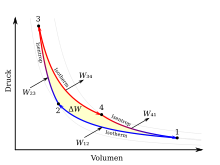
The Carnot cycle is made up of four changes in state, which are shown in the TS and pV diagram opposite . A red colored line corresponds to a hot volume and a blue one to a cold volume. Consider here the clockwise cycle for a heat engine. By reversing the process steps, the counterclockwise cycle for a heat pump follows. The work Δ W performed by the theoretical Carnot machine corresponds to the area enclosed by the lines 1234 in the pV diagram. At the same time, the area enclosed by lines 1234 in the TS diagram corresponds to the amount of heat Δ Q converted into work . For a better idea, a cylinder with a piston and ideal gas as the working medium should be thought of as a Carnot machine .
The individual process steps Ito are IVexplained below.
Isothermal compression
Process step I- line 1 → 2: The isothermal compression from volume V 1 to V 2 takes place at a constant temperature T K , the heat Q 12 being given off and the work W 12 being supplied. The gas volume becomes smaller, the pressure p rises, but the temperature is kept constant by cooling with the cold reservoir. Moving the piston takes work.
Since the change in internal energy d U = 0 applies to an ideal gas at constant temperature , it follows from the first law of thermodynamics that the entire compression work is dissipated as heat. In the diagrams, the integral for the amount of heat Q 12 is shown as the area under the line 1 → 2 in the TS diagram and the work W 12 as the area under the line 1 → 2 in the pV diagram.
Isentropic compression
Process Step II- line 2 → 3: The isentropic compression (also adiabatic reversible compression called) of V 2 to V 3 is carried out without heat exchange with the environment, whereby the temperature of the working medium from T K to T H changes. The gas volume becomes smaller, while pressure and temperature rise. Moving the piston requires work W 23 and is stored in the working gas as internal energy Δ U 23 .
Since there is no heat exchange with the environment (d Q 23 = 0), it follows from the first law of thermodynamics that the entire work of compression is converted into internal energy.
- κ = isentropic exponent (of the ideal gas)
- C V (mol) = molar heat capacity (of the ideal gas)
Isothermal expansion
Process step III- line 3 → 4: The isothermal expansion from volume V 3 to V 4 takes place at a constant temperature T H , the heat Q 34 being absorbed and the work W 34 being removed. The gas volume increases, the pressure decreases, but the temperature is kept constant by heating with the warm reservoir.
Isentropic expansion
Process Step IV- line 4 → 1: The isentropic expansion of V 4 to V 1 takes place without any heat exchange with the environment, whereby the temperature of the working medium from T H to T K changes. The gas volume increases, pressure and temperature drop. The piston is displaced while releasing the work W 41, for which the internal energy Δ U 41 (= Δ U 23 ) is withdrawn from the working gas .
Since there is no heat exchange with the environment d Q 41 = 0, it follows from the first law of thermodynamics that the entire work of expansion results from the loss of internal energy.
Efficiency
The first law of thermodynamics is
After running through the cycle, all state variables in the system, including the internal energy, reach their initial value ( ). The usable work is calculated from the integral along the path of the cycle:
- or.:
For the Carnot process we get for all :
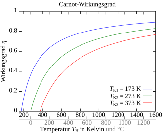
The Carnot efficiency indicates the ratio of work done to heat input. In order not to have a negative efficiency, the work done by the system must flow into the equation as an amount (da and ):
Perpetual motion of the second kind
In all four phases of the process, heat and mechanical energy are converted into one another. The total mechanical energy gained after running through the cycle depends only on the amount of heat supplied and removed. The mechanical work gained corresponds to the area highlighted in red in the TS diagram.
Since the lower temperature is always limited downwards and the upper temperature upwards, the Carnot efficiency is always below 1. Since, according to the third law of thermodynamics, it is not possible to reach the absolute zero point of the temperature, there is no real (cyclic working) machine that only extracts heat from a reservoir and converts it completely into work. A machine that is an efficiency would have greater than the Carnot efficiency at predetermined temperatures of the heat reservoir, called a perpetual motion machine of the second type. Finally, could be the reverse process can be run as a refrigerator at the obtained work again, and it could then a larger amount of heat are generated as that used in the heat engine process (comparison picture above ).
In thermodynamics, exergy is defined as the portion of thermal energy that can be used as work. Accordingly, the Carnot efficiency can also be expressed by:
The part of the thermal energy that cannot be converted into work is called anergy .
See also
- Absolute temperature
- Clausius-Rankine cycle
- Carnot method
- Carnotization
- Change of state
- Stirling engine
- Heat pump
- Chiller
literature
- Isabelle Stengers: Cosmopolitics I: The Science Wars, the Invention of Mechanics, Thermodynamics (PostHumanities) University of Minnesota Press, Minneapolis 2010. ISBN 978-0-8166-5686-8 .
Web links
- Video: CARNOT cycle - how much heat can be converted into work? . Jakob Günter Lauth (SciFox) 2013, made available by the Technical Information Library (TIB), doi : 10.5446 / 15659 .
Individual evidence
- ^ Carnot, Sadi (1824). Réflexions sur la puissance motrice du feu et sur les machines propres à développer cette puissance (in French). Paris: Bachelier.
- ↑ a b Technical Thermodynamics - An Introduction to Thermo- and Gas Dynamics . Springer-Verlag, 2013, ISBN 978-3-322-94776-5 , p. 67 ( limited preview in Google Book search).
- ^ Ulrich Hahn: Physics for Engineers . Walter de Gruyter, 2007, ISBN 978-3-486-59490-4 , p. 250 ( limited preview in Google Book Search).
- ↑ Jost Braun: Technical Thermodynamics Lecture-accompanying textbook . BoD - Books on Demand, 2014, ISBN 978-3-7386-0062-9 , pp. 116 ( limited preview in Google Book search).


