
DR 137 155
| DR 137 155 | |
|---|---|
 |
|
| Numbering: | 137 155 |
| Number: | 1 |
| Manufacturer: |
Westwaggon , Cologne -Deutz Maybach |
| Year of construction (s): | 1938 |
| Retirement: | 1958 |
| Axis formula : | (1A) 2'2 '(A1) |
| Genre : | BPwPostK8 VT-34 |
| Gauge : | 1435 mm ( standard gauge ) |
| Length over coupling: | 70 080 mm |
| Length: | Box length end car: 25 240 mm Box length middle car: 18 480 mm |
| Height: | 3594 mm |
| Width: | 2850 mm |
| Trunnion Distance: | End car: 18 870 mm Middle car: 18 660 mm |
| Bogie axle base: | 3000 mm |
| Empty mass: | 115 200 kg |
| Service mass: | 125 200 kg |
| Wheel set mass : | 16 355 kg (empty trolley) |
| Top speed: | 160 km / h |
| Installed capacity: | 2 × 441 kW |
| Performance indicator: | 7.66 kW / t |
| Wheel diameter: | 900 mm |
| Motor type: | Maybach GO6 |
| Motor type: | 2 × 12-cylinder V-engine with exhaust gas turbocharger |
| Power transmission: | hydraulic |
| Tank capacity: | 2 × 1000 l |
| Brake: | Air brake type Hildebrandt-Knorr SS, magnetic rail brake |
| Seats: | 100 |
| Floor height: | 1186 mm |
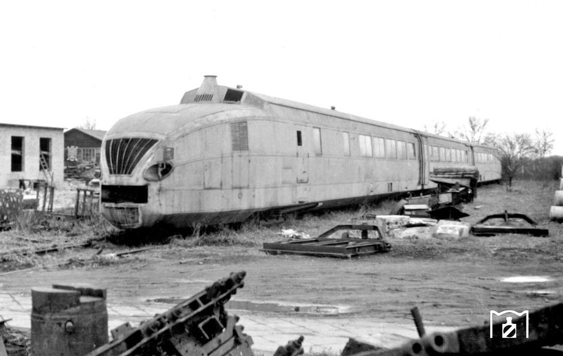
The railcar 137 155 , also known as the Kruckenberg express railcar or Fliegender Silberling , was a multiple unit of the Deutsche Reichsbahn that was built in 1938 for experimental purposes based on designs by Franz Kruckenberg . As a test vehicle, it was distinguished by its progressive concept and design . The special features were lightweight construction , air suspension and the pioneering power transmission with fluid drives that used water as the transmission medium.
history

The three-part multiple unit consisted of two machine cars and one intermediate car and had Jakobs bogies at the car crossings. On June 23, 1939, the 137 155 reached a speed of 215 km / h during a test drive on the Hamburg – Berlin route. During the testing phase, the drive wheel set shafts broke and, as the war began, they were not used again.
After 1945 the vehicle remained in the damaged car park of the Reichsbahn (DR) in the GDR . There it was retired in 1958 and scrapped in the Raw Wittenberge in 1967 . A motor bogie with the original fluid transmission was saved from scrapping by the Dresden Transport Museum. Backed up on a siding in the Dresden industrial area until the beginning of the 1990s , it can now be viewed together with an original Maybach GO6 engine in the Dresden Transport Museum. A fragment of a car body was discovered in an allotment garden in Wittenberge in 2014 and acquired by the Dresden Transport Museum.
The concept of the engine arrangement at both ends of the train and the raised driver's cabs behind it was decisive for the DB class VT 11.5 , which was built in the 1950s. The DR series VT 18.16 was also created with a similar drive concept.
Several features implemented for the first time in the DR 137 155 were implemented in a very similar form in the InterCityExperimental, which was designed from 1979 onwards (pivoting sliding doors, row of single seats on the opposite aisle side, multiple unit concept, air suspension (from ICE 2 ), aerodynamic power end shape ).
Constructive features
Car body

Compared to the conventional railcars of the time, the Kruckenberg express railcar had a modified and interesting suspension of the car body on the bogies. The short operating time and the conditions around the Second World War prevented thorough testing of the individual components, especially in the drive.
The drive was designed without a pivot. The specified dimensions of the pivot distance refer to the ideal pivot points. Pulling and braking forces were transferred from the bogie to the car body through two external handlebars and two angle levers. The free ends of the angle levers were connected by a rod, which was supported by a shock absorber from the car body. The non-powered Jakobs bogies basically had the same structure as the end bogies, only the upper parts were designed differently; the main suspension springs for the carriage support were installed transversely. This ensured that each side of the car body was supported on its upper part. The articulation of the bogies was done in the same way as for the end bogies.

The guidance of the car bodies in the Jakobs bogies was carried out in such a way that they were coupled by two spring-loaded rods guided in cast steel housings and connected by universal joints in such a way that the car bodies do not twist around the longitudinal axis, but perform angular movements horizontally and vertically, and longitudinal joints are spring-loaded could record. In order to keep the impact of the track dynamics small, the car bodies were guided in rubber ball supports in the bogie. The type of lever connections between the individual car segments was designed in the form of a torsion-resistant rod that only forced the rod to buckle when external forces occurred, for example when traveling in a curve or due to the dynamics of the carriage.
The car body was designed in the frame design with 17 longitudinal bars made of mostly cold-rolled profiles and cross-connecting frames under the windows, which were mainly connected by spot welding . The outer sheets were sheets with a thickness of 1.75 mm under the window parapet and 1.25 mm above. The front overhang of the machine wagons was particularly well stiffened by triangular girders and frameworks in order to obtain a dimensionally stable support for the machine system. The roof part in front of the driver's cab was removable. In addition, the lower side had to be opened by flaps so that the entire machine system could be removed from below.
The floor of the railcar in the passenger compartment was made of corrugated steel, it was filled with cork screed. On top of this was a layer of cork with a thickness of 4 mm as an insulating layer and a step covering 3.6 mm thick made of linoleum . The floor in the post compartment consisted of individual wooden planks, in the kitchen there was a stone floor. The management in the railcar was designed so that food and drinks were served at the seat. The seats in the single row had fixed tables, those in the double row had extendable tables.
The window panes were exceptionally large with a width of 1630 mm for individual compartments and 1730 mm for the remaining side windows. They were permanently installed. The front windows of the machine carriages were made of safety glass with a thickness of 8 mm.
The train's braking system was designed as a Hildebrandt-Knorr type compressed air brake , which was designed as a block brake on each wheel set. In addition, the multiple unit had a magnetic rail brake, which is common with the SVT . As a coupling option, the railcar had Scharfenberg couplings without a contact attachment. There was no multiple control.
Machine system

The engine system of the railcar was housed in the overhang of the end car. The diesel engine of type GO 6 and the flanged fluid transmission were placed at an angle in the overhang. The transmission to the second inner axle of the machine bogie, designed as the only drive axle, was carried out via a cardan shaft and a gear set. The engine and gearbox, along with some auxiliary equipment ( light starting machine , radiator fan ), were mounted on a rubber-sprung support frame that was supported on the main frame. The machine chamber was secured against the driver's cab by a double sheet steel wall with glass wool interlayer in a fire-proof and soundproofing manner.
The fluid transmission was designed as a two-converter transmission. Water with 3% anti-corrosion oil was chosen as the transmission medium. It was possible to start off in second gear even if the company was working properly. But a lower level of efficiency had to be accepted. The gearbox was shifted by hand.
The SVT Kruckenberg was equipped with reversing gears , which allowed the direction of travel to be changed at low speeds while coasting. In this form, the railcar was the only one on the Deutsche Reichsbahn with such a circuit. The prerequisite for this switchover was the complete draining of the fluid transmission.
The cooling elements were arranged in the machine chambers behind the diesel engine and above the fluid transmission. Each sub-vehicle of the multiple unit had an independent heating and ventilation system. In the summer, a fan forced fresh air into the passenger compartment through the fixed windows of the railcar, which left the car body underneath the windows as exhaust air. In the cold season, this air heater was supplied with warm air by an oil burner. As a rule, diesel was used for the oil burner, but lignite tar oil could also be used. The compressed air required for the railcar was generated by an electrically driven air compressor that was suspended from the underframe of the intermediate car. The on-board network was designed for a voltage of 110 V, and it was fed either by the lighting starter or the battery. The light starting machines could be used as a generator to feed the electrical system or motor for starting the associated diesel engine.
literature
- Heinz R. Kurz (Ed.): Flying trains. From the “Flying Hamburger” to the “Flying Cologne”. Eisenbahn-Kurier Verlag, Freiburg im Breisgau 1986, ISBN 3-88255-237-9 .
Web links
- Website about SVT Kruckenberg and the airline company on reichsbahntriebwagen.de
- VT 137 155 1960 stored in the Wittenberge repair shop at the Joachim Schmidt Railway Foundation
Individual evidence
- ↑ Discovery in the Elbe city: From the railcar to the shed In: Schweriner Volkszeitung. May 22, 2014.
- ↑ a b Heinz R. Kurz (Ed.): Flying trains. From the “Flying Hamburger” to the “Flying Cologne”. Eisenbahn-Kurier Verlag, Freiburg im Breisgau 1986, ISBN 3-88255-237-9 , p. 175.
- ↑ a b Heinz R. Kurz (Ed.): Flying trains. From the “Flying Hamburger” to the “Flying Cologne”. Eisenbahn-Kurier Verlag, Freiburg im Breisgau 1986, ISBN 3-88255-237-9 ; P. 174.
- ↑ Heinz R. Kurz (Ed.): Flying trains. From the “Flying Hamburger” to the “Flying Cologne”. Eisenbahn-Kurier Verlag, Freiburg im Breisgau 1986, ISBN 3-88255-237-9 , p. 176.
- ↑ Heinz R. Kurz (Ed.): Flying trains. From the “Flying Hamburger” to the “Flying Cologne”. Eisenbahn-Kurier Verlag, Freiburg im Breisgau 1986, ISBN 3-88255-237-9 , p. 177.