Three-phase machine
A three-phase machine converts mechanical energy into three-phase current or three-phase current into mechanical energy. It can be operated as an electric generator or as an electric motor . A three-phase motor is an electric motor that is operated with three-phase alternating current .
Basic principle
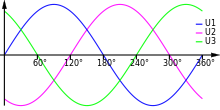
Three-phase motors are operated with three-phase alternating current or "three-phase current". This type of current carries its own periodically changing voltage in three separate conductors , the timing of which is offset by 120 ° leading or trailing in relation to the other two conductor voltages.
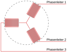
Fed to three solenoid - coils , each having a phase voltage phase of the three-phase system, then in each coil is the magnetic field , generated whose time sequence is the same as the voltage profile compared to the other coil fields offset by one third of a period.
If these three coils are arranged in a circle to one another, the result is a summed magnetic field from the individual coil magnetic fields, which is of constant size, but continuously changes its direction exactly in accordance with the frequency or the period repetition of the three-phase current. This summed up magnetic field "rotates" exactly at the speed specified by the frequency. With 50 cycle changes per second of the three-phase current (or 50 Hz ), the magnetic field also rotates 50 times per second (corresponding to 3000 times per minute).
If a magnetic object, for example a bar magnet or a simple iron body , is introduced into this rotating magnetic field on a centrally arranged axis , the runner, also known as the rotor , rotates with it.
Types
The types of three-phase machines are divided into two main groups, synchronous and asynchronous machines. These groups are divided into different types of rotor, as shown in the following diagram:
| Classification of the types of three-phase machines | |||||||||||||||||||||||||||||||||||||||||||||||||||||||||||||||||||||||||||||||||||||||||||||||||||||||||||||||||||||||||||||||||||||||||||||||||||||||||||||||||||||||||||||||||||||||||||||||||||||||||||||||||||||||||||||||||||||||||||||
|---|---|---|---|---|---|---|---|---|---|---|---|---|---|---|---|---|---|---|---|---|---|---|---|---|---|---|---|---|---|---|---|---|---|---|---|---|---|---|---|---|---|---|---|---|---|---|---|---|---|---|---|---|---|---|---|---|---|---|---|---|---|---|---|---|---|---|---|---|---|---|---|---|---|---|---|---|---|---|---|---|---|---|---|---|---|---|---|---|---|---|---|---|---|---|---|---|---|---|---|---|---|---|---|---|---|---|---|---|---|---|---|---|---|---|---|---|---|---|---|---|---|---|---|---|---|---|---|---|---|---|---|---|---|---|---|---|---|---|---|---|---|---|---|---|---|---|---|---|---|---|---|---|---|---|---|---|---|---|---|---|---|---|---|---|---|---|---|---|---|---|---|---|---|---|---|---|---|---|---|---|---|---|---|---|---|---|---|---|---|---|---|---|---|---|---|---|---|---|---|---|---|---|---|---|---|---|---|---|---|---|---|---|---|---|---|---|---|---|---|---|---|---|---|---|---|---|---|---|---|---|---|---|---|---|---|---|---|
|
|||||||||||||||||||||||||||||||||||||||||||||||||||||||||||||||||||||||||||||||||||||||||||||||||||||||||||||||||||||||||||||||||||||||||||||||||||||||||||||||||||||||||||||||||||||||||||||||||||||||||||||||||||||||||||||||||||||||||||||
Synchronous machine
With synchronous machines , the rotor always rotates synchronously with the rotating field . Depending on the type of rotor, a distinction is made between full - pole rotors , such as those used in turbo-generators , and slow-running salient pole machines . Both are electrically excited . Synchronous machines that are permanently excited with permanent magnets represent a special case . This area also includes the brushless DC motor, which also requires its own electronic commutation for operation.
Asynchronous machine
Three-phase asynchronous machines are available with the rotor as a squirrel cage rotor and as a slip ring rotor .
In the squirrel cage, the current conductors are short-circuited in the rotor body. In the similarly constructed slip ring rotor, the conductors have a connection to the outside via slip rings , which means that additional resistances can be introduced in the rotor circuit to influence the operating behavior. In both machine types, the rotating field of the stator induces a current flow in the conductor loops of the rotor and a magnetic field resulting therefrom, which is directed in the opposite direction to the magnetic field causing it. The resulting forces exert a torque on the rotor. If the stator field is allowed to rotate, it will 'drag' the rotor with it due to the effect described above. The rotor inevitably has a slightly lower speed than the stator rotating field; this is called slip . When the rotor and the rotating field run synchronously, there is no longer any induction, the transmittable torque is almost zero.
Direction of rotation reversal
To change the direction of rotation, the direction of rotation of the stator rotating field must be changed. When operating on a three-phase network, it is sufficient to swap two external conductors, e.g. B. outer conductors L1 and L3. A common circuit for this is the reversing contactor circuit .
In practical use, the motor terminals U2, V2 and W2 are bridged and
- for the right rotating field: L1 to U1, L2 to V1 and L3 to W1
- for the left rotating field: L1 to W1, L2 to V1 and L3 to U1
connected.
Coil arrangement of the stator
The effect of the three coils can be multiplied by distributing them in pairs opposite one another and in larger numbers over the circumference of the stator body. If each pair of coils is fed directly by the three-phase current with the mains frequency f , there is no change in speed. However, if several pairs of coils are connected in series for each of the three current phases and are distributed evenly over the stator circumference, the speed n of the resulting stator magnetic field is reduced in accordance with the number of coil pairs p involved .
This measure is carried out when low speeds and particularly quiet and even running with heavy loads are required. The standard speed for "single-pole" three-phase machines can only be increased by increasing the frequency or by using gearboxes .
Example: For a motor with four pairs of coils connected in series and distributed over the stator per phase, the number of revolutions N is in common units of measurement at a current frequency of 50 Hz :
- N = 50 Hz × 60 s / min: 4 coil pairs = 3000: 4 / min = 750 / min
Iron core
A further increase in efficiency results from the fact that the coil windings of both the rotor and the stator are embedded in a correspondingly shaped iron core . The permeability of iron leads to a multiplication of the magnetic flux and therefore also the acting driving forces and torques .
For practical implementation, the iron core cross-sections are always punched from thin and insulated dynamo sheet and put together to form a compact core. This is done to reduce eddy currents occurring in the iron core and the losses caused by them (as in the case of a transformer ) .
For the sake of simplicity, the winding grooves in the rotor iron core of asynchronous motors are filled with aluminum in production so that an electrically short-circuited aluminum conductor cage is created on the outer circumference of the iron core. During this casting process, cooling fan blades are usually cast on at the same time.
casing
The enclosing housing is not only used for protection, but also for the safe and secure accommodation of the stator core, the bearings for the rotor shaft and the electrical connection devices. The housing with its fastenings also serves as a counter bearing against the object driven by the rotor.
Another important function of the housing, especially with large engines, is heat dissipation . For this purpose, outer cooling fins are cooled by ventilation or water flows through cooling channels incorporated in the cast metal housing.
literature
- Gregor D. Häberle, Heinz O. Häberle: Transformers and electrical machines in power engineering systems. 2nd edition, Verlag Europa-Lehrmittel, Haan-Gruiten, 1990, ISBN 3-8085-5002-3
- Peter Bastian, Günter Springer: Electrical engineering expertise. 21. revised and exp. Edition, Verlag Europa-Lehrmittel, Haan-Gruiten, 1996, ISBN 3-8085-3431-1
- Günter Boy, Horst Flachmann, Otto Mai: The master's examination in electrical machines and control technology. 4th edition, Vogel Buchverlag, Würzburg, 1983, ISBN 3-8023-0725-9
See also
Web links
- Nominal values of three-phase motors ( MS Excel ; 26 kB)


