Bipolar
As a two-terminal network (including one-port or English. One Port Devices called) is known in the electrical engineering generally an electrical component or an electrical circuit with two "connections" (terminals). The extension is the quadrupole (two-port).
properties
According to the clamping behavior with sinusoidal alternating voltage, two-pole terminals are divided into three categories:
- Resistive : The current is proportional to the voltage, current and voltage are always in phase .
- inductive : the voltage is proportional to the change in current over time, the voltage leads the current .
- capacitive : the current is proportional to the change in voltage over time, the current leads the voltage .
There are mixed forms from the categories mentioned above: resistive-inductive, resistive-capacitive. An example of a resistive-inductive two-pole is an electric motor. An oscillating circuit can show all three behaviors depending on the frequency. A resonant circuit is often normalized by its resonance curve via the detuning , instead of being represented by a UI diagram.
In addition to these three categories, other properties of a two-pole can be determined:
- passive: The two-pole does not emit electrical power via the terminals in any operating state (on average over time).
- Active: There is at least one operating state in which the two-pole (on average over time) delivers power via the terminals.
- linear : The superposition theorem applies to the relationship between terminal current and terminal voltage .
- Time -invariant : The behavior of the two-terminal network is not explicitly dependent on time.
Equivalent circuits of linear two-pole connections
If only the terminal behavior of a linear two-terminal network and not its exact internal structure is of interest, this can be represented by a more compact equivalent circuit . The equivalent circuit has the same current-voltage behavior at the terminals as the original circuit.
Passive two-pole
If bipoles consist of purely passive elements, these are usually connected to one another by combinations of parallel connections and series connections and can easily be combined. In rare cases, however, it happens that three elements form a so-called star or triangle and prevent a direct combination. A star-delta transformation can, however, resolve such a problem area, which enables further summarization. If more than three switching elements form one of these problem areas, one speaks of stars and polygons and consequently the generalized star-polygon transformation .
The two-pole equation for passive two-pole is:
Active two-pole


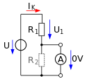
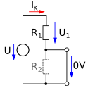
An equivalent circuit for an active two-terminal network consists of a backup power source or backup power source and an internal resistance . In the picture on the right, a simple voltage divider is shown as an example of a simple active two-pole circuit consisting of a voltage source U and two resistors R 1 , R 2 connected in series . The output voltage U 2 falls over the parallel circuit of R 2 and any connected load resistor R L from. The value of the equivalent voltage source shown on the right in the next picture, the so-called open circuit voltage , can either be measured at the output in the unloaded state without R L ( ) with a voltmeter or determined using the voltage divider rule. For the example, the value of the equivalent voltage source results as follows:
The short-circuit current is also required to determine the internal resistance . To do this, the output is short-circuited ( ). For a current measurement, this is done with an ammeter . A calculation reveals that the short circuit means that no more voltage drops across R 2 and that the following short circuit current results for the example:
With both values, the internal resistance of the equivalent circuit results as:
In purely mathematical terms, this solution for the internal resistance also results when the voltage source is short-circuited and the output is idle. Viewed from the output terminals , the internal resistance corresponds to the parallel connection of the two divider resistors. The second picture shows the equivalent circuit.
| Open circuit voltage | Short circuit current | Internal resistance | ||
|---|---|---|---|---|
| Measurement | invoice | Measurement | invoice | |

|

|

|

|

|
The load resistance R L remains unaffected by the changeover. It now forms a series circuit or voltage divider with R i and its effect on the output voltage is clearly evident. The larger it is ( ), the closer the output voltage approaches the open circuit voltage and the output current approaches zero. The smaller it is ( ), the closer the output voltage approaches the value 0 and the output current approaches the short-circuit current. The output voltage as a function of the output current expresses the two-pole equation:
The equivalent circuit can be converted into an equivalent circuit with an equivalent current source and internal conductance according to Norton's theorem . The two-pole equation depending on U 2 is then:
Power and efficiency of active two-pole systems
The output power is determined by:
The total output is:
The efficiency is calculated by:
The larger R L , the greater the efficiency. It can have values between 0 ( ) and 1 ( ). With power adjustment (maximum possible consumer power) ( ) it is 0.5.
Two-pole theory
The two-pole theory deals with the theoretical consideration and calculation of two-poles. The clamping behavior is described using the relationship between current and voltage , which can be frequency-dependent . If this relationship is entered in a two-dimensional diagram, different graphs are created depending on the component. This results characteristics , characteristic surfaces or individual points. However, a current-voltage diagram cannot be drawn for all elements.
literature
- Lorenz-Peter Schmidt, Gerd Schaller, Siegfried Martius: Basics of electrical engineering 3. Networks. Pearson Studium, Munich 2006, ISBN 3-8273-7107-4 .


