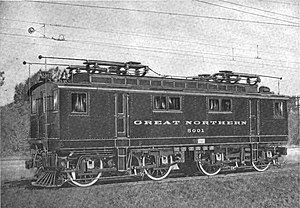
GN class 5000
| Great Northern Railway 5000 | |
|---|---|
|
GN No. 5001
|
|
| Numbering: | 5000-5003 |
| Number: | 4th |
| Manufacturer: | American Locomotive Company , General Electric |
| Year of construction (s): | 1909 |
| Retirement: | 1927 |
| Axis formula : | Bo'Bo ' |
| Gauge : | Standard gauge (1,435 mm ) |
| Length over coupling: | 13,411 mm (44 ft ) |
| Service mass: | 104 t (230,000 lb ) |
| Friction mass: | 104 t (230,000 lb) |
| Hourly output : |
without cooling fan: 1270 kW (1,700 HP ) with cooling fan: 1420 kW (1,900 HP) |
| Continuous output : |
without cooling fan: 746 kW (1,000 HP) with cooling fan: 1,600 kW (1,200 HP) |
| Starting tractive effort: | 210 kN (47,500 lb f ) |
| Power system : | 6,600 V , 25 Hz three-phase alternating current |
| Power transmission: | two-pole overhead contact line with a rail as the third conductor |
| Number of traction motors: | 4th |
| Brake: | Compressed air |
| Locomotive brake: | Compressed air brake, multi-release |
| Train heating: | no |
The Class 5000 of the Great Northern Railway comprised four electric locomotives built by the American Locomotive Company with the axle formula Bo'Bo ' . The electrical equipment for these boxcab locomotives was supplied by General Electric . They were the only locomotives in North America that were supplied with three-phase drive from a double-pole catenary .
technology
Mechanical part
The locomotives were intended for use at low speeds. The two two-axle bogies were fitted with a close coupling so that the locomotive body did not have to transmit any tractive forces. The locomotive frame was made of cast steel and could withstand impact forces of 2200 kN.
Electrical part
The power was supplied via the two pantographs with contact rollers attached to the contact wires and the rails as the third phase conductor for the three-phase alternating current . On the locomotive sat two 400 kW - Transformers the catenary voltage of 6600 V to 500 V down. The voltage was fed to the four traction motors, which were designed as eight-pole slip - ring motors . Traction motors and transformers were supplied with 270 m³ of cooling air per minute by a fan . Each engine had an hourly output of 350 kW if the cooling fan was running, otherwise one of 317 kW.
The approach took place with two drive motors, the other two motors were only switched on later. The pulling force was controlled by changing the starting resistors connected to the rotor circuit. The motors did not have pole changing, so there was only one speed step. When driving downhill, the motors switched to generator operation without any further action, so that the locomotives had a regenerative brake without additional circuitry . The excess energy in the network was converted into heat by water resistances in the power plant.
The axle drives were designed as pin bearing drives with a two-stage gearbox. The cooling air is routed to the traction motors through a cavity in the cradle of the bogie.
The locomotives are equipped with multiple controls.
commitment
The four kilometer long Cascade Tunnel , built between 1897 and 1900, was used by steam locomotives after it opened . The problem was the 17 ‰ slope, which had to be overcome by the eastbound trains.
The electric locomotives ordered in June 1907 were delivered in February 1909 and used in operational service from July 1909. They were only used to move trains through the tunnel at 25 km / h. About three passenger trains and three freight trains ran in each direction every day. The freight trains were carried with three locomotives, whereby the trailer load could be a maximum of 1600 t; only two locomotives were used in the passenger trains weighing a maximum of 700 t.
Whereabouts
In 1927, the GN abandoned the three-phase system and electrified the line with 11 kV, 25 Hz single-phase alternating current. All 4 locomotives were decommissioned and replaced by the Z-1 class .
literature
- William D. Middleton: When the Steam Railroads Electrified . Kalmbach Books, Milwaukee, WI 1974.
Web links
- Ben Ringnalda: Great Northern Electric Rosters. In: The Great Northern Empire - Then and Now. Retrieved November 30, 2019 .
Individual evidence
- ↑ a b c d e f g Edward P. Burch: Electric traction for railway trains . McGraw-Hill Book Company, New York 1911, Great Northern Railway, p. 349-353 ( archive.org ).
- ^ A b Three-phase locomotives of the Great Northern Railroad . In: Electrical engineering and mechanical engineering . tape 26 , issue 47, p. 1032 .
