Gas diffusion electrode
Gas diffusion electrodes are electrodes in which the three physical states - solid, liquid and gaseous - are in contact and the solid, electron- conducting catalyst catalyzes an electrochemical reaction between the liquid and the gaseous phase. The solid catalyst is usually pressed into a porous film with a thickness of around 200 μm .
Their use in fuel cells is particularly well-known , in which the gases hydrogen and oxygen are converted into water and electrical energy in a kind of cold combustion .
Pore system
An important prerequisite for the operation of gas diffusion electrodes is that both the liquid and the gaseous phase can be present in the pore system of the electrodes at the same time. How this can be achieved can be seen from the Young-Laplace equation :
The gas pressure p is thus related to the liquid in the pore system via the pore radius r, the surface tension σ of the liquid and the wetting angle Θ . However, this equation is only intended as a guide, because too many parameters are unknown or difficult to determine:
- For surface tension, the difference between the surface tension of the solid and the liquid must be considered. The surface tension of catalysts such as Pt on carbon or silver can hardly be measured.
- The wetting angle on a flat surface can still be determined with a microscope. A single pore, however, cannot be examined. The pore system of an entire electrode is always determined.
In order to create space for liquid and gas in an electrode, one can choose to create different pore radii r or different wetting angles Θ . The next two chapters explain how this was done.
Sintered electrodes
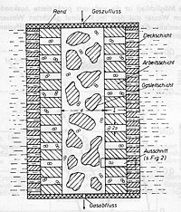
In the picture of the sintered electrode you can see that three different grain sizes were used, which formed different layers:
- 1: Top layer made of fine-grained material
- 2: Working shift from different groups
- 3: Gas-conducting layer made of coarse-grained material
Many electrodes were manufactured in this way between 1950 and 1970 for use in fuel cells . At VARTA , Siemens u. a. Pilot productions ready. However, this type of production was dropped for economic reasons because
- the electrodes were thick and heavy - 2 mm thick was common;
- the individual layers had to be very thin but flawless;
- the metal price for this type of electrode was too high;
- the electrodes could not be manufactured continuously.
In the picture "Principle of the gas diffusion electrode" its structure is shown again. The so-called gas-conducting layer is located in the middle of the electrode. With only a small excess gas pressure, the electrolyte is displaced from this pore system. A small flow resistance ensures that the gas can spread unhindered along the electrode. With a slightly increased gas pressure, the electrolyte in the pore system of the working layer is also displaced, albeit only partially. The top layer itself is selected with such fine pores that gas can get through the electrode into the electrolyte even in the event of pressure peaks.
Such electrodes were produced by sprinkling and subsequent sintering or hot pressing. In order to produce multi-layer electrodes, a fine-grained material was first scattered into a die and smoothed. Then the other materials were applied in layers on top of each other and then pressed together. Production was not only error-prone, but also time-consuming and difficult to automate.
Plastic bonded electrodes

Therefore, since about 1970, another approach has been taken to produce an electrode with both hydrophilic and hydrophobic areas, because with the introduction of PTFE a material is available which
- is chemically very resistant,
- can be used as a binding agent,
- has a hydrophobic effect.
For the pore system, this means that no electrolyte can penetrate at the points with a high PTFE content, but at points with a low PTFE content. In this case, of course, the catalyst itself must not also have a hydrophobic character.
There are two technical ways of producing such PTFE-catalyst mixtures:
- Dispersion of water, PTFE, catalyst and emulsifiers, thickeners, ...
- Dry mixture of PTFE powder and catalyst powder
The dispersion route is mainly chosen for electrodes with polymer electrolytes - e.g. B. successfully introduced in the PEM fuel cell PEM or HCL membrane electrolysis. The dry process is more suitable when used in liquid electrolytes. It is true that mechanical pressing can be dispensed with in the dispersion route by evaporating the water and sintering the PTFE at 340 ° C. This makes these electrodes very open-pored. On the other hand, if the drying conditions are incorrect, cracks can quickly develop in the electrode, through which liquid electrolyte can penetrate. This is why the dry-mix process has become established for applications with liquid electrolytes such as zinc-air batteries or the AFC alkaline fuel cell.
In addition to these wetting properties, the electrode must of course have an optimal electronic conductivity so that the electrons can be transported with the lowest possible ohmic resistance.
Catalysts
Ultimately, the right choice of catalyst is crucial. For catalysis in acidic electrolytes, noble metal catalysts such as platinum, ruthenium, iridium and rhenium have prevailed. In alkaline systems such as the zinc-air battery, inexpensive catalysts such as carbon, manganese or silver can be used.
Technical parameters
In order to quantify the properties of the gas diffusion electrode, the following parameters are given:
- Thickness [µm]
- Sheet resistance [Ω * cm²]
- Permeability according to Gurley Precision Instruments [s] or permeation measurement for gases permeation
- Overvoltage (electrochemistry) [V]
Due to the small thickness of gas diffusion electrodes, the sheet resistance is also very low. With these geometries, the resistances cannot be determined using the 4-point method . Therefore, the gas diffusion electrode is measured between two gold-plated stamps under high pressure in order to minimize contact resistance.
In fact, the gas transport in the electrodes takes place via diffusion and not via convection. Therefore, the pressure should not be set too high when measuring the permeability. At Gurley this is fixed at 1296 [Pa] (or 12 [mbar]).
The overvoltage is the most complex measurement test. Stable power supplies, potentiostat , a stable reference electrode and a special test cell are used to measure it. Due to the high current density in gas diffusion electrodes, particular attention must be paid to a constant field lines. A large distance to the counter electrode and a tubular electrolyte space are recommended for this. The Haber-Luggin capillary must also not disturb the course of the field lines.
commitment
Initially, the gas diffusion electrodes were developed for use in fuel cells . The Bacon cell for converting coal into electricity at high temperatures was still being worked on until 1950, but in the 1950s there was a tendency to convert gases into electricity, especially hydrogen due to its high reactivity. Over time, however, a wide variety of uses in other applications have emerged:
- Zinc-air battery since 1980
- Nickel-metal hydride battery since 1990
- Hydrochloric acid electrolysis since 2003
- Chlor-alkali electrolysis since 2011
A current research area is the use of gas diffusion electrodes in the electrochemical conversion of carbon dioxide .
Web links
- Gas diffusion electrode and method for its production EP 2398101 A1 (accessed on September 11, 2015)
- Gas diffusion electrodes for PEM fuel cells by in situ electrode deposition (accessed on September 11, 2015)
Individual evidence
- ↑ Devin T. Whipple, Paul JA Kenis, Prospects of CO 2 Utilization via Direct Heterogeneous Electrochemical Reduction J. Phys. Chem. Lett. 2010, 1, 3451-3458 doi : 10.1021 / jz1012627


