Patch cord
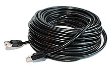
A patch cable (Engl. To patch - interconnect), and patch cords is a cable type of network technology and telecommunications . Patch cables are usually pre-assembled . The term patch cable originally refers to short cable lengths (e.g. 50 cm or 1 m), but there is no specific cable standard, which is why any variable, non-fixed cable connections are often referred to as patch cables. Patch cables or connection cables are available in both fiber optic and copper versions (for example twisted pair or twinax (coaxial) patch cables for Ethernet or InfiniBand ).
With copper patch cables, the cores in the cable consist of flexible copper strands in contrast to fixed cables, which consist of solid wires . With fiber optic patch cables , a complex cable structure is dispensed with and more flexible Zipcord variants are generally used for duplex (two easily separable, separated fiber optic cables ). The length of patch cables is usually around 0.3 to 25 m; fixed connections are usually used for longer distances.
Copper patch cables are either wired one-to-one (the same positions of both plugs are connected to one another) or certain wire pairs are crossed ( cross cable ).
use
The patch cable is used
- for connection of terminals ( ports ) of a patch panels (also Patch called) with ports of another patch panel; This compound is called patch or ranking
- for connecting connections (ports) of a patch field with a network distribution device ( e.g. switch , hub or router )
- the connection of end devices (e.g. PC with network card ) to a power socket.
Types
Patch cables are used in various network types, for example in
- Ethernet networks, defined according to the international standard TIA / EIA-568A / B
- structured cabling
- Telephone distributors for telephone systems
Common cable types are mainly twisted pair cables , but also coaxial cables and fiber optic cables .
For categories of cable quality (Cat-1 to Cat-8) see twisted pair cables .
Manufacture of copper patch cables
In principle, patch cables for twisted-pair copper applications can be assembled relatively easily yourself. However, it must be taken into account that the quality and quality of a patch cable has a significant influence on the performance and quality of the data transmission. The wire diameter and the quality of the yard goods play a role here, as do the connector and the quality of the assembly. Factors such as Power over Ethernet and the associated possible problems with the plug connection should not be disregarded here. It is recommended to use fully certified and tested ready-made patch cables.
wiring
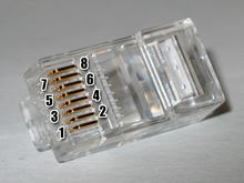
Regardless of the standard actually used, the contacts of 8P8C plugs and sockets are numbered as follows:
According to the standard used, the contacts according to TIA-568A / B for 100BASE-TX are wired as follows:
The only difference between TIA-568A and TIA-568B is the interchanging of the colors of wire pairs 2 and 3 (orange and green). Both standards wire the contacts one-to-one. Since the wiring is the same for both standards apart from the wire colors, the cables have the same function. It is important that both ends of a cable are wired according to the same standard (one to one).
For historical reasons, TIA-568B is still fairly widespread in the USA. In Europe, wiring is generally carried out in accordance with TIA-568A, as this assignment corresponds to the general color codes of telephone installations.
production
If you manufacture patch cables for Ethernet according to the 1000BASE-T or 100BASE-TX standard, then, in addition to the wrong cable quality ( Cat 5 or better is required), twisting is a frequent source of error. If the twisting with ISDN or 10BASE-T is still almost without influence due to the relatively low signal frequencies, it is of major importance with 100 Mbit or Gigabit.
Ethernet with twisted pair cable uses symmetrical differential signals to minimize electromagnetic radiation. It is therefore important which wire pairs are twisted together. This works (idealized) as follows: If there is a positive voltage on one wire of the pair of wires, there is also an equally high negative voltage on the other wire, which means that the electromagnetic fields that arise cancel each other out. The same applies analogously to the effects of external fields; if the radiation increases the voltage on one of the twisted wires by 5 volts, for example, this also increases the voltage on the other wire by 5 volts (due to the twist), which means that the differential signal is the same remains, i.e. the irradiation has no influence on the signals. In any case, with 1000BASE-T and 100BASE-TX, pins 1 and 2 must form a twisted wire pair; the same applies to the wire pair on pins 3 and 6 (with 1000BASE-T and 100BASE-T4 cables, pins 4–5 and 7–8 twisted pairs). In addition, all wires of a pair of wires should be exactly the same length as possible and the twisting may only be missing or removed on a short piece of cable (max. Approx. 1.5 cm).
These types of errors can only be detected by expensive high-frequency cable testers (but so can some Gigabit Ethernet network cards). The simple LED testers, on the other hand, work with direct current and therefore do not show which wire pairs are twisted. Of course, all of this also applies analogously to 10BASE-T cabling, whereby incorrectly twisted wire pairs are far less disturbing here.
Manufacture of fiber optic patch cords
When assembling fiber optic or fiber optic patch cables, the required fibers (with duplex a transmit (TX transmitter ) and a receive fiber (RX receiver )) are removed with a special tool and glued into the ferrule (connector sleeve) of a fiber optic connector . The excess fiber is then scored and broken down in a defined manner. As the next step, the face of the connector is then ground flat with a polishing set . The strain relief of the patch cable is realized by means of a crimp sleeve on the connector body, which is clamped under the Kevlar thread responsible for the relief . The cable jacket and the anti-kink sleeve to be attached to the connector or cable transition provide additional mechanical protection. The quality and quality of a patch cable is largely determined by factors such as the accuracy of the core drilling in the ferrule, core eccentricity and roundness of the glass fiber used and the quality of the polishing. The smallest grooves and impurities on the fiber end face can, depending on the power density of the laser transmission, lead to massive damage to the connector system and other components. Apart from that, contamination and poor assembly quality quickly lead to an increase in the system attenuation and increase the bit error rate. It is all the more important that the end faces are individually assessed and checked by an interferometer during production and that the quality of the raw materials used is continuously high. Efforts are being made to reduce the sensitivity of such fiber optic patch cords through new techniques and further developments in order to make them more user-friendly.
literature
- Hans Joachim Geist: Large practical book of communication technology. 1st edition. Elektor-Verlag, Aachen 2001, ISBN 3-89576-109-5
- Rudolf Huttary: Household electrics and electronics. 3. Edition. Franzis Verlag, Poing 2001, ISBN 3-7723-4803-3
Web links
- Build twisted pair patch cables according to EIA / TIA-568B yourself
- Cable assignments
- Connector types for fiber optic cables ( Memento from April 2, 2015 in the Internet Archive ), at lwl-kabel.ch


