
Prussian AT 1
| Prussian AT 1 | |
|---|---|
 |
|
| Numbering: | 1751 Mainz - 1755 Mainz |
| Number: | 5 |
| Manufacturer: | Hw Tempelhof, SSW, AfA Berlin |
| Year of construction (s): | 1907 (year of renovation) |
| Retirement: | 1943 |
| Axis formula : | A 1 A |
| Type : | Direct current accumulator railcar |
| Genre : | AT 1 |
| Gauge : | 1435 mm ( standard gauge ) |
| Length over buffers: | 12,200 mm |
| Length: | 10,100 mm |
| Height: | 4,180 mm |
| Width: | 2,890 mm |
| Total wheelbase: | 6,000 mm |
| Service mass: | 33.5 t |
| Friction mass: | 14.0 t |
| Top speed: | 45 km / h |
| Capacity: | 200 Ah |
| Driving wheel diameter: | 1000 mm |
| Impeller diameter: | 1000 mm |
| Drive battery: | 180 elements type IV GC 126 |
| Power system : | Direct current lead / battery |
| Number of traction motors: | 2 |
| Drive: | Direct current series motor |
| Type of speed switch: | Travel switch |
| Brake: | Resistance brake |
| Train heating: | Pressed coal heating |
| Coupling type: | Screw coupling |
| Seats: | 60 |
| Classes : | III |
The Prussian AT 1 were three-axle accumulator railcars with two driven end axles and a non-powered central axle. They were built in 1907 in the main workshop in Tempelhof using three-axle passenger cars according to sample sheet 18a. The electrical part was supplied by the company Schuckert Nuremberg and the drive batteries by the company AFA Berlin .
development
The Palatine railways tested from 1896 different " Omnibus cars with electric or gas engine drive". From May 25 to December 31, 1896, the two battery- powered railcars provided free of charge by the delivery company covered 20,796 km on the narrow-gauge route between Ludwigshafen and Mundenheim and carried 72,400 people. In 1897 the mileage of the vehicles was 36,285 km, they were then returned to the delivery company.
procurement
Due to the good operating results at the Palatinate Railways, the board of directors of the Prussian-Hessian State Railways also decided to try this type of drive. The theoretical preparatory work required for this was started by the Prussian Ministry for Public Works as early as 1897. The Erfurt-Langensalza, Cüstrin-Frankfurt adOder and Alzey-Gau Algesheim routes were to be used for the trial operation. The project failed because of the high cost of the electrical energy required for charging the batteries. By ministerial decree of November 23, 1904, the work was stopped.
On August 1, 1904, Gustav Wittfeld took over the management of the new department for the application of electrical engineering in railways. Driven by him, investigations began again in 1905 for the use of accumulator railcars on new, suitable routes. In 1906 Wittfeld arranged for the main workshop in Berlin-Tempelhof to convert a total of five three-axle compartment cars according to drawing 18a to accumulator railcars. The cars were given elevated driver's cabs at both ends, the electrical components were supplied by SSW ( Siemens-Schuckert-Werke , Nuremberg), and the lead batteries by AFA .
Although the wagons proved themselves very well in the test operation, no further procurement took place. The reasons were the difficult access to the accumulator batteries during assembly / dismantling and the unpleasant odor of the passengers due to the arrangement under the seats. The meanwhile greatly increased volume of traffic required a larger number of passenger seats as well as the requirement for fourth-class passengers that came with the class reform. With the AT 3 wagons already being procured , these requirements were met to the full satisfaction.
commitment

At the beginning of 1907, the five vehicles from 1751 Mainz to 1755 Mainz were used from the Mainz train station. In trial operation, they drove into the gaps in long-distance traffic as local trains to Oppenheim , Ingelheim and Rüsselsheim-Raunheim . The average daily output was initially 60 km, later 100 km.
After the trial operation was completed, the wagons drove six times a day to Rüsselsheim and four times each to Ingelheim and Oppenheim. From October 1, 1907, the trips beyond Ingelheim were extended to Gau-Algesheim . The loading point for the vehicles was in Mainz.
Whereabouts
All cars were taken over by the Deutsche Reichsbahn in 1920 and assigned to the Mainz directorate. They were given the company numbers 201 to 205 and the class designation AT 1 .
After the delivery of the new AT 3 cars , their use was increasingly restricted. In 1920 the car 205 was located in Darmstadt, where it was used for the shuttle service between the main train station and Darmstadt-Kranichstein . The car was also used for school traffic.
Of the remaining wagons, the 201, 204 and 205 were located in Hamm in 1927 when a charging station was put into operation there. They were used for staff trips. The last Reichsbahn multiple unit was retired in 1943.
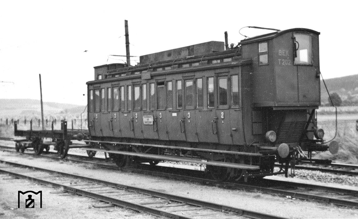
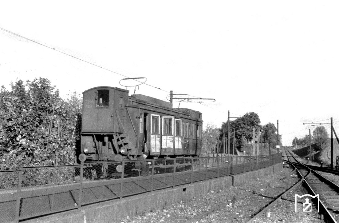
Bad Eilsener Kleinbahn T 202 and T 203
After 1920 the AT 202 and AT 203 were sold to the Bad Eilsener Kleinbahn . The two cars designated as T 202 and T 203 drove here in regular passenger train service. After the Bad Eilsener Kleinbahn was converted to 600 V = overhead line operation in 1926, the batteries were removed from the two railcars, the controls were rebuilt, the middle axle was removed to reduce weight and two Lyra pantographs were added. The car, which was popularly known as Minchen , was given more space with 100 seats in six compartments, one of which was in 2nd class. In addition, the pulling force increased; so they could now carry two sidecars. They have been in use in this form for more than 30 years. The T 203 was the first to be retired in 1953, followed by the T 202 in 1961 .
Constructive features
Underframe
The frame was completely riveted together from steel profiles. Screw couplings were installed as a pulling device and rod buffers as a pushing device . To both sides were fitted with continuous ascent boards . There was no transition option.
Car body
The car body was a wooden frame construction clad with sheet metal. The side walls were slightly drawn in at the bottom, the car roof had a flat curve and a skylight attachment. The entire appearance corresponded to that of a compartment car . At both ends, raised, slightly eccentric driver's cabs were built in the style of a brakeman's cab. This form of cab extensions made it possible to use the end compartments without restriction.
In order to divert the exhaust gases produced by discharging the batteries, there were ventilation hoods on the side walls at the level of the affected bench seats. On the top of the skylight there was still a structure to accommodate the drag brakes.
drive
The drive and wheel sets were designed as steering wheel sets . The electrical resistance brakes on the car roof were available as the only service brakes. The spindle hand brakes available in the driver's cabs at each end of the car only served as a parking brake and only acted on the respective drive axle.
Passenger compartment
The cars had individual compartments without any connection to one another. The high cabs were located at both ends of the car. There were four third class compartments. Another compartment of the third class could also be used for the second class if necessary. There were six outward opening compartment doors on each side of the vehicle for quick passenger changes. The compartments were equipped with wooden slatted benches.
The lighting was carried out with electric light bulbs, the electricity was taken from the accumulators. The wagons were heated by externally charged press charcoal ovens, which were installed under the side members. Ventilation took place through skylight windows on the car roof, and the compartment door windows could also be opened.
drive
It was driven by two four-pole main current motors of 25 kW each . To start up, the motors were connected in series, after reaching 25 km / h they were connected in parallel. The power supply was ensured by a total of 180 type IV GC 126 batteries with a capacity of 200 Ah per cell. With them, a distance of 60 km was possible without recharging the batteries. Later, more powerful batteries of the type 6 TM 300 were installed in the vehicles, which enabled the mileage to be increased to 100 km. During the journey all cells were connected in series. The storage elements were installed under the folding seats. To change, they could be lifted out through the doors using a lifting device. The batteries were ventilated by static fans (pitot tubes) in the side walls.
Wagon numbers
| Manufacturing data | Track numbers for each epoch, generic symbols |
||||||
|---|---|---|---|---|---|---|---|
| Samples leaf |
Construction year | Manufacturer | Number | until 1910 | from 1910 | from 1920 | from 1926 |
| AA | AT 1 | AT 1 | AT 1 | ||||
| 1907 | Hw Tempelhof, Schuckert and AfA | 5 | 1 751 to 1 755 | 1 851 to 1 855 | AT 201, AT 204, AT 205 Bad Eilsener Kleinbahn T 202 and T 203 |
AT 201, AT 204, AT 205 Bad Eilsener Kleinbahn T 202 and T 203 |
|
literature
- Andreas Wagner, Dieter Bäzold, Rainer Zschech: Locomotive Archive Prussia, Volume 4 . Bechtermünz Verlag, Augsburg 1996, ISBN 3-86047-573-8 .
- Dieter Bäzold, Dr. Rolf Löttgers, Dr. Günther Scheingraber, Manfred Weisbrod: Railway Journal Archive . In: Prussia Report . Issue 9. H. Merker Verlag GmbH, Fürstenfeldbruck 1996, ISBN 3-922404-84-7 .
Individual evidence
- ↑ Wagner, Bäzold, Zschech 1996, page 142 ff.
- ↑ Bäzold, Löttgers, Scheingraber, Weisbrod 1996, page 58 ff.
- ↑ a b Bäzold, Löttgers, Scheingraber, Weisbrod 1996, page 59
- ↑ a b c Wolff: Deutsche Klein- und Privatbahnen Volume 11 Lower Saxony Part 3, EK-Verlag Freiburg, 2009, ISBN 978-3-88255-670-4 , page 56
- ^ Image of the T 202, 1953, Joachim Schmidt Railway Foundation
- ^ Picture of the T 203, 1948, Joachim Schmidt Railway Foundation
- ↑ Wolff: Deutsche Klein- und Privatbahnen Volume 11 Lower Saxony Part 3, EK-Verlag Freiburg, 2009, ISBN 978-3-88255-670-4 , page 59