
Integrated truss structure
| Integrated truss structure | ||||||||||||||||||||||
|---|---|---|---|---|---|---|---|---|---|---|---|---|---|---|---|---|---|---|---|---|---|---|
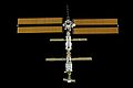
 ISS in June 2017
|
||||||||||||||||||||||
| Space station: | International space station | |||||||||||||||||||||
| Adjacent modules | ||||||||||||||||||||||
|
||||||||||||||||||||||
The Integrated Truss Structure ( ITS ; German: Integrated Lattice Structure ) is the load-bearing lattice structure of the International Space Station (ISS). It forms their backbone and is oriented across the direction of flight.
Like the entire space station, the ITS has a modular structure. The individual elements are labeled with a combination of letters and numbers ("P" stands for port, from English port; "S" stands for starboard, from English starboard): P1, P3 / 4, P5 and P6 are on the left in the direction of flight arranged, while the elements S1, S3 / 4, S5 and S6 are mounted on the right side. Element S0 is in the middle and is connected to the inhabited part of the station via the Destiny Laboratory.
The Integrated Truss Structure is a trapezoidal, rigid light metal structure with additional cross struts. A special "Module-to-Truss Segment Attachment System" is used to connect the individual segments of the lattice structure. For each connection there is a remote-controlled catch bolt that connects both elements loosely and then tightened. In addition, four motor-driven bolts that are additionally secured then engage.
The grid structures were manufactured by Boeing , while Lockheed Martin manufactured the radiator and solar cell surfaces for NASA .
Lattice structure
|
|
||||||
| element | mission | Start date | Length (m) |
Width (m) |
Height (m) |
Mass (kg) |
|---|---|---|---|---|---|---|
| Z1 grid element | 3A - STS-92 | October 11, 2000 | 4.9 | 4.2 | 8,755 | |
| P6 grid element - solar panel | 4A - STS-97 | December 1, 2000 | 10.67 | 4.87 | 4.9 | 15,873 |
| S0 grid element | 8A - STS-110 | April 8, 2002 | 13.4 | 4.6 | 13,970 | |
| S1 grid element | 9A - STS-112 | October 7, 2002 | 13.7 | 4.57 | 3.96 | 12,572 |
| P1 grid element | 11A - STS-113 | November 24, 2002 | 13.7 | 4.57 | 3.96 | 12,477 |
| P3 / P4 grid element - solar panel | 12A - STS-115 | September 9, 2006 | 13.8 | 4.88 | 4.75 | 15,900 |
| P5 grid element | 12A.1 - STS-116 | December 10, 2006 | 4.55 | 4.24 | 1,864 | |
| S3 / S4 grid element - solar panel | 13A - STS-117 | June 8, 2007 | 13.8 | 4.88 | 4.75 | 16,183 |
| S5 grid element | 13A.1 - STS-118 | August 8, 2007 | 3.37 | 4.55 | 4.24 | 1,819 |
| P6 grid element - repositioning | 10A - STS-120 | October 23, 2007 | - | - | - | - |
| S6 grid element - solar panel | 15A - STS-119 | March 15, 2009 | 13.4 | 4.9 | 4.9 | 15,824 |
| S2 and P2 have been canceled. | ||||||
| 1B | 3A | 2A | 4B | |||||||||
| S6 | S5 | S4 | S3 | S1 | S0 | P1 | P3 | P4 | P5 | P6 | ||
| 3B | 1A | 4A | 2 B | |||||||||
Integrated Truss Structure Z1

The Z1 grid element (“Z” stands for zenith ) was brought to the space station by the STS-92 mission in October 2000 and mounted on top of the Unity module . Four gyroscopes are installed in the Z1 to control the position of the station, along with motors and heaters. The gyros each have a mass of 315 kg and reach a maximum speed of 6,600 revolutions per minute ( angular momentum : about 2,300 Js). Its dimensions are 4.9 m × 4.2 m with a total weight of 8.8 t. Two communication antennas for data and video images are mounted on Z1. In the construction phase of the station, Z1 was also used as a support for the P6 lattice mast with its solar panels . Therefore, power converters are also part of the equipment. Inside the module there is a small storage space that is used to store equipment and spare parts. This is accessible from Unity Zenit through a lockable hatch.
Integrated Truss Structure S0
Starboard Zero S0 ( English for starboard zero ) is the central segment of the 100 m long lattice structure of the International Space Station , which was installed by the STS-110 mission in April 2002 . S0 is connected to the Destiny laboratory module via extendable telescopic supports .

The S0 grid element is 13.47 m long, 4.57 m wide, has a mass of 12,118 kg and consists of five individual bays. It also has a system for automatic connection to supply lines (energy, data, coolant ), a 6.40 m long radiator for radiating excess heat (especially from the energy systems), a portable work platform, four GPS antennas for determining the position of the station , an independent system made up of two measuring complexes with three ring lasers each , which determine the accelerations in all three axes and calculate the position of the station using a computer, a detector for charged particles , four energy switching units, two circuit breakers, three halogen headlights, two independent control systems for remote control of the most important functions, a large number of supply cables with automatic connection devices as well as rails on the front-facing side for the mobile transporter (MT).
The MT is an aluminum construction, 2.74 m long, 2.62 m wide and 97 cm high. It has a mass of 885 kg and runs on rails along the lattice structure. Complex software takes over the control of the 20 motors for driving, locking and connecting the energy couplings. The mobile transporter has ten docking points on the individual grid segments. When locked, there is a contact pressure of around 30 kN between the rail and the transporter. The maximum payload is 20.9 t.

The grid element Z1 (zenith 1) of the ISS with four gyroscopes

Z1 grid element during the start preparations

ISS lattice structure S0 during transport from the loading bay of the space shuttle

Astronauts from the STS-113 mission are working on the P1 grid segment
ISS on October 9, 2000, after installing the P6 energy module

The ISS with the first three parts of the lattice structure: S1 - S0 - P1
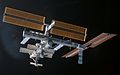
the ISS after installing the P3 / P4 truss (right)


Integrated Truss Structure P1 and S1

Portside One P1 was launched on November 24, 2002 aboard the Endeavor ( STS-113 ) and Starboard One S1 was launched on board Atlantis ( STS-112 ) on October 7, 2002 , and both entered central orbit three days later Module S0 coupled. The two elements are each about 14 meters long, 4.57 meters wide and have a mass of 12.5 tons. They each have a system for the automatic connection of supply lines (energy, data, coolant), a coolant tank, this includes a nitrogen tank, three radiators , each 22 m long to radiate excess heat (especially from the energy systems), along with the associated rotating mechanism and Control electronics, power converters and distributors, two video connection stations, two passive and one active segment connection systems as well as one transport cart each (CETA 1 and 2). There are differences in the installed communication system, S1 has an S-band antenna, P1 a UHF communication system.
Integrated Truss Structure P2 and S2
The elements P2 and S2 were originally intended as drive elements, but became superfluous due to the Russian participation in the station.
Integrated Truss Structure P3 / P4 and S3 / S4


Both elements each consist of two individual segments that were connected to one another before the start: the grid structures P3 and S3 and the solar cell carriers P4 and S4. They differ slightly from each other: P3 / P4 is 13.81 meters long, 4.88 meters wide, has a height of 4.75 meters and has a mass of 15.8 tons. S3 / S4 is 13.66 meters long, 4.96 meters wide and 4.63 meters high with a mass of 16.2 tons.
The P3 (S3) element is rotatably connected via the SARJ (Solar Alpha Rotary Joint) to the P4 (S4) element, on which there are two foldable solar cell wings that are used to generate energy. The blades are rotatable and can be aligned perpendicular to the sun. Inside the grid structure of the P4 (S4) element there are batteries for storing the generated energy. There is also a radiator on the element, which releases excess heat into space and thus cools the electronics of the solar collector.
The P3 / P4 element was brought into orbit with the space shuttle mission STS-115 in September 2006 and mounted on the P1 carrier.
S3 / S4 was brought to the ISS on the STS-117 mission in June 2007 and mounted on segment S1.
Integrated Truss Structure P5 and S5

The segments P5 and S5 are each a 3.37 m long adapter piece to be able to mount the P6 and S6 solar modules on the P4 and S4 solar modules.
The P5 structure was transported to the ISS with the STS-116 (ISS 12A.1) mission in December 2006 and the S5 structure in August 2007 with the STS-118 (ISS 13A.1) mission.
Integrated Truss Structure P6 and S6
P6 and S6 are the outermost segments of the Integrated Truss Structure. Both consist of a grid structure as well as solar cell surfaces.
P6 was brought into space during the STS-97 mission and initially attached to base Z1 on December 3, 2000. During the STS-120 mission on October 30, 2007, it was relocated to its final location on the port-side (left in flight direction) part of the ISS, the P5 element.
With the S6 element, the last element of the Integrated Truss Structure was brought into space with the STS-119 mission . On March 19, 2009 it was attached to the S5 element. This completed the construction of the Integrated Truss Structure.
Modules
Solar panels

In addition to the smaller solar cells on the Russian modules, which were mainly used at the start of construction, the ISS has four large solar elements.
There are two solar cell carriers at the ends of the ITS grid structure: elements P6 and P4 on the port side and S6 and S4 on the starboard side. The elements can be rotated 360 ° so that they are always optimally aligned with the sun.
Each of the eight solar cell surfaces is 35.05 m long and 11.58 m wide when unfolded. A surface with a mass of 1.1 t consists of 32,800 individual solar cells, which are combined into strips of 400 pieces each. One panel is made of 82 strips and can generate 32.8 kW direct current. Since both surfaces are unfolded in opposite directions, they have a total span of 73 m.
Each solar cell surface (solar array wing) consists of a foldable lattice mast, two foldable solar cell panels, tensioning wires for extending or retracting the panels and devices for their control. There are also facilities for stabilizing and storing electrical energy and for cooling all systems. The electric current reaches three charging systems with two nickel-hydrogen batteries each via 82 lines per panel . The voltage is regulated to around 140 V.
Theoretically, 31 kW can be used. Power can be provided for the control, the cooling equipment and the station at the same time. The batteries are also charged (maximum 3 × 8.4 kW per solar cell surface).
The cooling system consists of heat sinks with cooling fins that are in direct contact with the heat-generating parts, several cooling circuits with ammonia as the coolant , electric pumps and a radiator, which theoretically has 14 kW radiation output. All systems together have a power requirement of more than 6 kW, which is therefore not available for use in the space station.
In summary, it is more of a small power plant than a solar system for generating electricity. The complex systems are controlled by several computers, maintained during the operation of the space station and replaced if necessary. The S6 energy module alone cost around $ 1.2 billion.
Accumulators
The nickel-hydrogen batteries provide the power for the station while it is in the shadow of the earth. They are installed in elements S4, P4, S6 and P6. Each battery consists of 38 individual cells, has 38,000 charge-discharge cycles, an estimated service life of six and a half years and a weight of 187 kg.
Solar Alpha Rotary Joint
The Solar Alpha Rotary Joint (SARJ) is a swivel joint that has the task of tracking the solar panels precisely to the sun in order to guarantee the best possible energy generation. To do this, the solar cell surfaces are rotated so that the sun falls perpendicularly on the solar cells. The individual solar wings can also be rotated around a second axis - called Beta Gimbal Assembly (BGA) - at their fastenings.
There are two SARJs, the first connecting segments P3 and P4 and the second connecting segments S3 and S4. The two joints have the shape of a wagon wheel and rotate the respective ends of the lattice structure, consisting of elements S4, S5 and S6 as well as P4, P5 and P6. All electrical connections are made via slip rings so that the joint does not have to be turned back.
With a diameter of 3.20 meters, a length of 1.02 meters and a mass of 1.1 tons, the SARJ can be rotated over 360 degrees with an accuracy of one degree. The SARJ was built by Lockheed Martin .
The starboard SARJ was found to be extremely worn during 2008, the problem was corrected during the STS-126 mission.
Crew and Equipment Translation Aid (CETA)

There are also two CETA platforms on the Integrated Truss Structure. The Crew and Equipment Translation Aid (abbreviated CETA, English for crew and equipment transport aid ) is a mobile, handcart-like small platform that can be moved on the rails of the lattice structure. It consists of an aluminum plate with fasteners for payloads attached, with guide wheels, locking devices, shock absorbers and various containers. It has a mass of 283 kg, is 2.50 m long, 2.36 m wide and 0.89 m high. With the outriggers folded in, CETA can be moved from one side of the mobile transporter to the other. Both systems use the same rail system.
While the Mobile Transporter is intended for the transport of loads of up to around 20 t in weight, CETA serves as an easy-to-use transport system for space travelers and smaller payloads.
Web links
- NASA Integrated Truss Structure (English)
- NASA page about P3 / P4 (English)
Individual evidence
- ↑ Lockheed Martin: Press release on the solar panels started with STS-115 ( page no longer available , search in web archives ) Info: The link was automatically marked as defective. Please check the link according to the instructions and then remove this notice. , August 21, 2006 (English)
- ↑ http://www.lockheedmartin.com/news/press_releases/2006/MassiveLockheedMartinSolarArraysBeL.html ( page no longer available , search in web archives ) Info: The link was automatically marked as defective. Please check the link according to the instructions and then remove this notice.

Sarja · Unity · PMA · Zvezda · Integrated Truss Structure · Destiny · ESP · Mobile Servicing System · Canadarm2 · Quest · Pirs · Strela · Harmony · Columbus · Kibō · Canada Hand · Poisk · ELC-1, 2 3 & 4 · Tranquility · Cupola · Rassvet · PMM Leonardo · Alpha magnetic spectrometer · BEAM
Modules to be started: Bishop · Nauka · ERA · SPM · Axiom
Painted modules: CAM · habitation module · ICM · IPM · Research Modules · SPP · UDM · DSM · MPM Enterprise · Crew Return Vehicle