Compound steam engine
A compound engine or multiple expansion engine (engl. Compound engine ) is a steam engine with at least two successively switched in vapor direction of work units. In 1874 Anatole Mallet applied for a patent for the use of the composite principle in locomotive construction .
The effective efficiency of a compound steam engine with heated jackets and receiver was given in 1893 as 7.2%.
Discontinuous compound, piston engines
function
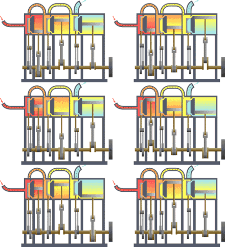
In a piston composite steam engine, the high-pressure steam in the first cylinder expands to a medium pressure . After this first expansion, the partially expanded steam is not released into the atmosphere or fed to a condenser , as is the case with the simple machine, but fed with its residual pressure to another cylinder unit to carry out further work , which with a larger displacement the work capacity of the already expanded to larger volume Steam portion continues to work off at lower pressure. Because the temperature reduction of the steam is distributed over spatially separated machine parts in the composite working method, the surface damage is reduced ; the steam loses less heat on cool walls than with single-stage expansion (= cooling).
This multi-stage (more than two stages are also possible) use of the steam pressure results in better utilization of the specific energy contained in the steam ( enthalpy ). The composite steam engines are therefore more economical in terms of fuel and water consumption than comparable steam engines with single-stage steam expansion. At the exit of the last cylinder there is usually a condenser in which the steam is liquefied and the water is returned to the circuit.
use
The principle of the compound steam engine was used in steam locomotives with two, three and four cylinder engines . It is also possible to implement more than two stages of steam pressure utilization in piston engines that are connected in series.
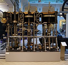
Quadruple expansion machines were very rare because of their size and runnability. The first machine of this type was built into the Kaiser Friedrich in 1898 . It had five cylinders that worked on three cranks. The low pressure was processed in two cylinders, all other stages consisted of only one cylinder.
construction
During the development of compound steam engines, it was recognized that due to the partial expansion of the steam in the high-pressure cylinder, a larger area was required for the low-pressure cylinder, because piston rods of different lengths were ruled out due to practical considerations. First of all, the area of the low-pressure cylinder was doubled in relation to the high-pressure cylinder because it was assumed that the steam pressure would be halved. In the case of three-cylinder compound machines with double steam expansion, this favored the development of designs with one high-pressure and two low-pressure cylinders, each with the same diameter. With increasing experience in the construction and operation of compound steam engines, the effective area of the low pressure was then further enlarged in order to optimize the energy yield. In the case of triple steam expansion, the ratio of the cylinder areas was treated accordingly. For the calculation, the area of the medium pressure cylinder in relation to the low pressure cylinder was treated as if the medium pressure cylinder were a high pressure cylinder.
Expressed in numbers, there is the following ratio of cylinder areas or piston diameters:
- with two or four cylinders and double steam expansion:
- Cylindrical surfaces:
- High pressure: low pressure = 1: (2.25 ... 3)
- Piston diameter:
- High pressure: low pressure = 1: (1.5 ... 1.7)
- with three cylinders and double steam expansion (after optimization of the total cylinder area):
- Cylindrical surfaces:
- High pressure: low pressure = 1: 2 × (1.125 ... 1.5)
- Piston diameter:
- High pressure: low pressure = 1: 2 × (1.06 ... 1.23)
- with three cylinders and triple steam expansion:
- Cylindrical surfaces:
- High pressure: Medium pressure: Low pressure = 1: (2.25… 2.8): (5… 7)
- Piston diameter:
- High pressure: Medium pressure: Low pressure = 1: (1.5… 1.7): (2.25… 2.7)
- with four cylinders and triple steam expansion:
- Cylindrical surfaces:
- High pressure: Medium pressure: Low pressure = 1: (2.25 ... 2.8): 2 × (2.5 ... 3.5)
- Piston diameter:
- High pressure: Medium pressure: Low pressure = 1: (1.5… 1.7): 2 × (1.59… 1.87)
The crank offset was chosen in such a way that the crank forces of the various cylinders acted on the drive axis with approximately the same strength; in two- and four-cylinder machines it was 90 °. With three-cylinder machines there was obviously a lack of clarity about the optimal crank offset; some machines were built with a 120 ° crank offset, e.g. B. the locomotives of the Swiss class B 3/4 . As a result, an almost even torque and a good mass balance were achieved. The French engineer Michel Andrade received the first patent for a locomotive with such a power unit in 1875, but its design failed due to mechanical problems. But there were also constructions that had 90 ° crank offset between the low-pressure cylinders and 135 ° between the low-pressure and high-pressure cylinders with double steam expansion, e.g. As the freight locomotives of the Württemberg Series G . There were even entire series that were otherwise identical, some with a crank offset of 120 ° and some with 90 ° + 2 × 135 ° crank offset and were put into service.
The advantage of better energy use is offset by some disadvantages of the composite principle: on the one hand, the construction costs of several cylinders, pistons and the slide or control devices. A problem with the stringing together of several differently sized expansion units is also the regulation. With changing load cases (steam locomotive) it is almost impossible to optimally set both the high pressure stage and the low pressure stage. One of the influencing possibilities, the steam volume control, always has an effect on both stages, since there is no intermediate escape of steam. As a rule, there was no separate influencing of the individual drives in order not to make the control mechanics too complex. Special devices were also required for starting such a steam engine.
Continuous network, turbo machines
Almost every steam turbine today is a compound steam engine. The expansion of the steam takes place in the longitudinal direction of the turbine in a graduated diameter from small impeller diameters (for the boiler pressure) to ever larger impeller diameters (close to the ambient pressure) in order to convert the forms of energy (from thermal energy into mechanical energy ) as close as possible to the thermodynamically maximum possible to reach.
literature
- Erich Preuss: Lexicon inventors and inventions railroad. 1st edition. Transpress Verlag for Transport, Berlin 1986, ISBN 3-344-00053-5 .
- Johannes Schwarze, Werner Deinert, Lothar Frase and others: The steam locomotive. Reprint of the 2nd edition (1965). transpress Verlagsgesellschaft, Berlin 1993, ISBN 3-344-70791-4 .
- K. Bösche, K.-H Hochhaus, H. Pollem, J. Taggesell: Steamers, Diesel and Turbines - The World of Ship Engineers . Convent Verlag, Hamburg 2005, ISBN 3-934613-85-3 .
Individual evidence
- ↑ Rudolf Diesel: Theory and construction of a rational heat engine to replace the steam engine and the combustion engines known today. Springer, Berlin, 1893, ISBN 978-3-642-64949-3 . P. 51
- ↑ O. Flamm: The latest successes in German trade and warship construction. In: Stahl und Eisen - Zeitschrift für das Deutsche Eisenhüttenwesen, Volume 17, Part 2, 1897


